No matter how smart modern TVs are, they still sometimes fail. This can be affected by breakdowns of external devices, internal components of the TV, or software failures. Problems manifest themselves in different ways. The most unpleasant consequence is that for some reason the Samsung TV does not turn on . Not everyone can deal with this problem on their own, but we are here to help fix the problem.
Typical defects in the power supply of Samsung TVs
Samsung CK-3339ZR. The mains fuses are blowing. The power supply is assembled using the SEC3S0680RF IC. The reason turned out to be a cracked capacitor C805 2n2/800V. Changed capacitance to 330nF. After replacing it with 2200 pF/3kV (from ULPTsT) everything works.
Samsung CS-5062Z (chassis P68SM-H). The image shows a group of embossed lines moving vertically. The defect resembles interference from a switching power supply. When the demagnetization loop is turned off, the picture becomes normal. After replacing the thermistor in the demagnetization loop circuit, the malfunction disappeared.
Samsung CK-5051A. Smoked. Exploded capacitor C853 along the +125V circuit. The horizontal scan output transistor Q402 is broken, R826 is open. The damage listed above is a consequence of excess voltage at the output of the power supply. When searching for the cause of the overvoltage at the output of the power supply, a ring crack was discovered around pin No. 9 of IC801 type SDH209B, and it was also discovered that C852 had lost capacity.
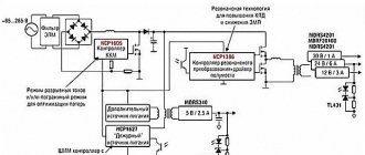
Samsung TV. SMR 40200 and HIS 0169 in the power supply. In operating mode 125 volts, in standby mode 200 volts (R2K is broken into 2 parts). I tried changing the set of chips - the same result. After a detailed check, the 2200pF x 800 Volt capacitor turned out to be faulty (located between the radiator fins). SAMSUNG CK-3339ZR, the power supply is covered. The SMR40200 chip has failed. Replaced it. I checked the zener diode R2N - intact. I disconnected the 110 volt circuit going to the TDKS. I plugged it into the network with a 60-watt incandescent lamp instead of the mains fuse - the lamp lit up brightly. The HISO169B microassembly turned out to be faulty. If I turned it on without a lamp, the SMR40200 crashed. After removing the protective layer, the 1P transistor in the microassembly turned out to be faulty. Replacement with KT3117A. The TV is working fine.
SAMSUNG many models with power supply based on SMR40200 (SMR-40000) and HIS-0169. Malfunction: increased supply voltage of the horizontal scan cascade in “STANDBY” mode 160-170 V instead of 140V. Under load, in the “POWER ON” mode, the voltage is normal: 125-127 V. Replacing SMR and HIS does not help. Way out of the situation: the inductor (black) connected between legs 3 and 4 of HIS-0169 is faulty. It should be replaced with a homemade one: wind 40 turns of PEL wire diam. 10 (1000-2000 nm) on a ferrite ring. 0.4(0.3 - 0.5) mm.
SAMSUNG CS-2085R arrived after a thunderstorm, the power supply does not start. Near R803 and R804 there are visible traces of an arc discharge. The ZD803 27v zener diode in the power circuit of the power microcircuit has failed. KA5Q0765RT survived, works great even without a zener diode, but just in case I replaced it with a new one. After repairing the power supply, the TV does not exit standby mode. I thought the TDA9381PS/N1/3S0250 had failed, but as soon as I updated the firmware on the Orange-2 programmer from a working device, everything worked.
Samsung CX-558 chass P-88M TDA4601 does not start the power supply, artificially supplying 12v there is generation on the 7-pin microcircuit, output B+ instead of 125v there is only 20v, replace C812 1.0/50v.
Samsung CK-5320TR. I installed a new “couple” SMR40200 and HIS0169. . “Stand by” voltage is 170V, I tried the recommendations from the internet (R=130oM between the 3rd leg HIS0169 and the L803 inductor, wound a new L803 inductor, installed a C851 47.0*25V capacitor instead of 22.0*35) nothing helps. It was possible to achieve correct operation of the power supply by selecting the C803 2200pF to 1500 pF (options are possible). Voltage “Stand by” 137V operating 124-126V replaced the inductor with the standard one, resistor R=130оМ and capacitor C851 47.0*25V left.
SAMSUNG SMR40200 & HIS0169. To reduce the output voltages in standby mode, it’s a good idea to try replacing the capacitor C852 according to the diagram, namely, increasing the capacitance from 1nF to 2nF. And put a resistance of 330 Ohms in series with the choke. For those without a circuit, use 2 SMR legs through 10 Ohms, through this connector, to the common minus. Just in case, connect a 2-3uF 400V capacitor minus to the microassembly into the gap of 1 leg of the HIS. In standby mode 140V the temperature is within 40 degrees, in operation 127V the temperature is about 50 degrees.
SAMSUNG CK-5038/39/73/85 etc. (Chassis SCT11A,B,D…). The power supply is built on SMR-40200 and HIS-0169. Perhaps, as recommended in secret No. 36, it is necessary to replace the inductor L803 so that Uout does not increase. with power supply in dez. mode (for this reason, SMR-40200 are flying, and not because of their low reliability, which traders immediately took advantage of and inflated prices for SMR-40200 to sky-high heights!!). But I recently discovered and tested another method, apparently many already know it, but nevertheless. In one of the latest modifications of the SAMSUNG CK-5085 on the Chassis SCT11, I noticed a modification in the power supply, possibly done in a service workshop. Between pin 3 of the HIS-0169 microassembly and pin L803, a track on the board was cut and an MLT-0.125 130 Ohm resistor was installed. On occasion, I checked this find in another device. After replacing the burnt out R2KN and line transistor (SMR-40200 and HIS-0169 in this case withstood) the voltage in the supply. mode it was about 150-160 V. I quickly turn off the device, do the modification described above and everything is OK, Uout. dez. about 135-140V, in operating mode 130V, which is the norm. Now, when repairing power supplies on SMR-40200 and HIS-0169, I make sure to modify it.
SAMSUNG CK-3382ZR (chassis P69SA1 04). When turned on, the standby LED will blink once and that’s it. Power supply for STR-S6707. After checking the parts of the power supply, a faulty diode was discovered (according to circuit D824), which was leaking. The diode was replaced with RGP-10. After that, the TV turned on, the voltage was 125V normal.
Samsung CK-3351. The power supply is assembled on SDH209B. Fault: output voltage is too low. C852 470.0x16V failed. After the replacement everything worked.
When is a master needed?
Hardware failures can only be repaired by a qualified technician. Therefore, if the power supply of your Samsung Smart TV has burned out or dots appear on the screen, be sure to contact a service center for help.
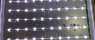
The image is too dim
This symptom indicates that there are problems with the backlight. The fact is that all the LEDs are connected in series, so if one lamp burns out, you have to completely change the entire system. It is not uncommon for the backlight to stop working due to voltage problems. In some situations, a dim picture is a sign of problems with the LED driver.
No sound
TV restoration involves testing the performance of the power supply, as well as the entire chain: from the adapter to the chip responsible for playing audio tracks. It is possible that the power supply is working, but the microcircuit is damaged.
Line scan defects on Samsung TVs
Samsung CS-21K3S Plano does not turn on. Short in line transistor D5703. When replacing, the liner fails again. Checking the stitcher's binding did not yield anything. The horizontal deflection system turned out to be faulty.
SAMSUNG CK 2185VR. The same capacitor caused the following malfunction. Image as with a small accelerating voltage. The voltage at the accelerating terminal of the kinescope did not rise above 240 volts. After replacing the 10nF-3kW capacitor in the accelerating circuit, the voltage increased and the image became normal. SAMSUNG 3385 When the power is turned on, the red LED blinks continuously - indicating a malfunction. Analysis of the signals showed the presence of horizontal scan trigger pulses and a non-working output stage. The reason is a break in the primary winding of the interstage line transformer. W1=400 vit., W2= 45 vit. Wind the windings in one direction. Wire with a diameter of 0.15mm and 0.6mm, respectively.
SAMSUNG CK-5385ZR. The malfunction was as follows: there is no startup when the TV is turned on, the indicator lights up yellow and immediately red, and then starts flashing red every half a second. Apparently some water got in through the back cover and rotted the wires of the primary winding of the TMS (T401). SAMSUNG CK5341ZR. The image is shifted horizontally. The H-SHIFT control has no effect. Defect: leakage of capacitor C404 2700pF.
Pressing cables
After playing with pressing the train, the idea was born to simply press them in the right places with the appropriate design. double-sided tape along the entire screen to the metal frame that is located on top of the matrix from the inside This is so that the pressure is uniform everywhere and no new mechanical stress arises.
On this strip of tape I glued
a strip of sealing material in which motherboards and other computer parts are packaged.
It turned out that there will be a sealing pad just opposite the contact of the cable with the matrix .
This is where she will lie down.
The meaning of the idea is to press the cables to the matrix.
After assembling this miracle, it turned out that the thickness of the seal was not enough. I chose a thicker seal.
And I glued this seal directly to the junction of the cables with the Samsung LE40A454C1 matrix.
Frame scanning defects
Samsung SCT11D. Strong twist of the frame from above. Zener diodes DZ301 and DZ303 (33v and 22v respectively) are broken.
SAMSUNG chassis SCT11B came with a faulty TDKS. After replacing it with a new one, horizontal scanning started, but not frame scanning. The TA8445K turned out to be operational, there are no startup pulses. On the VPG101T ceramic assembly, the first transistor turned out to be broken (in a working VPG, a resistance of 100 kOhm is measured between legs 1 and 5 with a digital multimeter, and in the diode test mode, the base-emitter junction of the first transistor is measured). After replacing C1Y on the assembly with a regular PNP transistor, it turned out that the vertical scan trigger pulses do not come from the 18th leg of the M52309SP. I did it as in secret No. 325, started the personnel one from pin 19 of the M52309SP, and everything worked. Two transistors and a resistor solved the problem of replacing the M52309SP and VPG101T.
SAMSUNG CK-5051(P68SA chassis). Defect: periodically does not turn on from standby mode; when you press the CH buttons, quiet clicks are heard. Malfunction: capacitor C855 dried out (after desoldering, traces of electrolyte were found under it), which led to a drop in the supply voltage at the moment of switching on from the container. mode.
Samsung CK5366. There is no frame scan. Blame the krenka - 1С805.
Samsung CW28C73W. Chassis KS3A. Received for repair with a defect: periodic disappearance of the image. Checking the V-SYNC and H-SYNC pulses showed that at pin No. 11 of the VDP3120B the H-SYNC amplitude is only 2 volts. At the same time, the constant voltage mode was overestimated - about 3V. The fault is with D203 (RB441Q), the reverse current of which periodically increased and then disappeared.
SAMSUNG CK-5373 does not have a raster, there is sound for all programs. According to the owner, it broke down with a howl when the heater was turned on in the tee, where the TV was already turned on. When adding SCREEN, a raster with noise appeared, but there are graphics. In the tuning mode, you can hear from the sound that the programs are being tuned on all ranges. After replacing the 24C04 memory, everything worked even without adjustment in SERV. Along the way, a defect with which the owner had been putting up with for probably a year was eliminated in the same device. The strong curl from below in the frames with warming up decreased, but was not completely eliminated. C303 2.2 µF on the fifth pin of TA8445K.
SAMSUNG CK-564BZR, The screen is dark, there is OSD and sound. AT pin 22 of the TDA 8844 the voltage is 0 V. Leakage in C255 (0.1 µF). After replacing the C255, the image appeared. Samsung CK-5385ZBR after a thunderstorm. The power supply is live, there is no +5V on the SZM-137M3, the processor itself shorted. I changed it, the TV turned on, but there was no frame. I looked at it with an oscilloscope - indeed, on the 18th leg of the M52309SP the pulses are greatly underestimated. I used the 19th - it didn’t help, VPG101 also crashed. I replaced it, the scan appeared, but the image rattled vertically. I had to change M52309SP as well.
SAMSUNG CK-5373ZR screen is pressed from bottom to top white stripes - replace C308 3.3X50V
SAMSUNG CK-564BZR, The screen is dark, there is OSD and sound. AT pin 22 of the TDA 8844 the voltage is 0 V. Leakage in C255 (0.1 µF). After replacing the C255, the image appeared. Samsung CW-5083V. There is sound and TV control. No raster. Line scanning is all normal. Added SCREEN - a narrow, horizontal, bright stripe appeared in the center of the screen. There is no frame scan. CR launch pulses are present. At 41 pins of the TDA8362B there is 4.6V. By pin 41 of the TDA8362B, the video path is locked in the event of a malfunction of the control system, when on pin 41. the voltage becomes less than 1V or more than 4V.