Concept Basics
In the modern world, saturated with gadgets and technology, only a few can independently find a direction of interest using a compass and map.
The ability to find azimuth can be useful and help out in any business. True (geographic) azimuth is a dihedral angle, measured clockwise (from 0 to 360 degrees) from the northern geographic meridian to the direction line.
Magnetic azimuth is the angle formed by the magnetic meridian and the given direction of the landmark line. The countdown is clockwise (from 0 to 360 degrees). Finding an angle can be done using compasses and compasses. Magnetic azimuth is not accurate, since the compass needle points to the magnetic meridian, which is subject to annual changes.
Magnetic declination is the angle of difference between the true and magnetic meridian, which was mentioned earlier. It can be positive if the compass needle is deviated from the true meridian to the right, or negative if it is deviated to the left. On maps, magnetic declination is indicated relative to the year of printing. Each subsequent year of operation, the provided data can be adjusted.
Naturally, the magnetic declination for each region and location varies.
A topographic map of an area is used for various purposes. It is a universal map, with the maximum amount of information about a particular region. A topographic map is divided by parallels (horizontal lines) and meridians (vertical lines). The map is convenient for orientation using a compass. Geographic data of a place contains information about the terrain, soils, waters, roads and other terrain features.
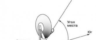
Determining the direction to the satellite by the sun
Nowadays, more and more people are installing satellite television.
Tricolor TV, Telekarta, NTV PLUS, Raduga TV - all these operators can offer good quality pictures. But questions continue to come regarding the location of the antenna installation. The most common question is the possibility of receiving a specific satellite operator. Quite often, when people are thinking about installing a satellite dish, they wonder whether it is possible for them to install a satellite dish? Of course, the easiest way would be to consult a specialist. But as we know, people are quite curious and often clients try to independently determine the direction to the satellite before ordering. In this article we will try to help them with this.
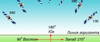
First, you should know that the sun rises in the east and sets in the west. Next, find the satellite you are interested in in the table above and see at what time the sun is in approximately the same position as the desired satellite. Wait for this time and find the sun in the sky. At approximately this position, and maybe even a little lower or higher, vertically, the satellite of the desired satellite operator is located. And the satellite dish must be pointed exactly at the satellite. This direction should under no circumstances be blocked by trees, high-rise buildings, etc.
You need to know that the closer the satellite is to the south, the higher it is located above the horizon, and the further to the west or east, the lower it is located.
It follows from this that installing equipment on a higher satellite is much easier than installing equipment on a lower satellite, due to many obstacles: trees, houses, various structures.
Well, if you are not able to determine the direction to the satellite yourself, or you simply do not want to bother with it, then do not bother yourself with various calculations. It is much easier to call our company on a short telephone number and get the necessary information. You will receive a fairly extensive answer to your question. Well, or you can call a specialist who will promptly take all the necessary measurements and, if possible, carry out the installation immediately.
Source
Finding values and working with acquired parameters
Information regarding the determination of azimuth will be discussed next.
- Plan for determining true azimuth (using a magnetic compass):
- The compass is aligned horizontally to the ground, allowing the magnetic needle to point north;
- The desired object is determined and a reference point is taken;
- Without changing the position, adjust the compass bulb to the arrow, so that the letter N (C) is clearly opposite the magnetic pointer;
- The degree is counted by compass divisions, from zero to the given direction line of the object (clockwise);
- Result – magnetic azimuth was obtained;
- The magnetic declination of the region is added or subtracted to the found degree;
- And so, the true azimuth has been found.
- Calculation of azimuth on the map:
- The desired landmark is selected and marked on the map with a dot;
- Next, from the intended landmark, a continuous line is drawn from the starting point to the marked area;
- From the starting point, a parallel straight line is projected relative to the geographic meridian;
- Having two drawn lines, the protractor finds the angle that will be equal to the true azimuth.
Calculation by coordinates is similar to the process of finding azimuth on a map. Instead of a marked landmark on the map, the coordinates of the point are taken and the direction is plotted.
- Reverse azimuth.
The desired direction, determined by a compass or map, changes by one hundred and eighty degrees, receiving a reverse calculation.
Benefits of the acquired information:
- One of the ways to receive mirror data from the opposite direction point.
- The ability to make an accurate turn and follow the path back.
which direction to point the “satellite dish”
- Platform HD
- Orient Express (Orion)
- Tricolor Siberia
- NTV Plus East
- Surface Plus (Ukraine)
- Viasat (Ukraine)
Specify the antenna installation address. By dragging the pointer on the map, you can clarify its location.
Antenna coordinates:
Satellite:
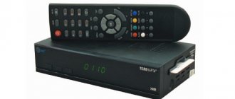
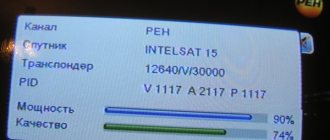
To install the antenna yourself without any equipment, follow the following instructions. Determine the landmark on the map according to which you will align and secure the antenna in a horizontal plane. Tilt the antenna to its lowest position. Rotate the converter to the required angle (usually the markings are already applied to the converter itself). Connect the antenna cord to the antenna and receiver, connect the receiver to the TV, and turn them on. Switch to any TV channel on the receiver and enter the information menu (usually by pressing the INFO button on the remote control). The screen should display two scales - signal level and signal quality with values close to zero. Gradually begin to raise the antenna mirror in increments of 0.5 cm and a delay of 2-3 seconds, until the signal level is more than 90 and the quality is more than 70. Also, most likely, a TV picture will be displayed on the screen. Fix the antenna in a horizontal plane. Register your smart card with your carrier if necessary.
Azimuth:
The value for plotting the direction with a protractor on the map.
Magnetic azimuth:
Value for deferring compass direction.
Tilt angle:
How much to tilt the antenna mirror relative to the surface of the earth. It is quite normal for the antenna to tilt towards the ground.
Elevation angle:
With negative and close to zero values, signal reception from the satellite is impossible.
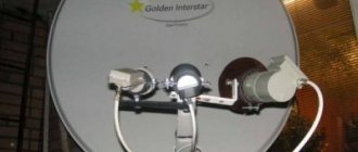
Converter rotation:
If you look at the converter the way a plate looks at it, then you need to turn it clockwise for a positive value, and counterclockwise for a negative value.
When broadcasting a satellite in circular polarization (Tricolor, NTV+), the converter does not need to be turned.
Source
Application of azimuth data in the field of satellite antennas
A correctly calculated azimuth, whether using a map or compass, will not only tell you the way back home, but will also help with setting up a satellite dish.
The main guidance parameters will be considered the angular coordinates of the orientation of the antenna beam axis in elevation and, of course, azimuth. Before installing the antenna, you need to decide from which satellite the signal will be received. The coordinates of various satellites can be found on thematic websites or at an antenna purchase store. Knowing the orbital position of the satellite, you can calculate the azimuth and elevation angle.
Elevation angle is a degree value in the vertical plane, characterizing the angle between the horizontal and the direction towards the satellite.
This value is calculated using a special protractor or devices based on the operation of an accelerometer. Also, if you have a modern smartphone, you can download software from the Internet that performs data measurements. This will definitely help the user adjust the antenna to the selected angle.
The direction of the satellite antenna in the vertical plane can be lined up using a compass by performing a calculation with the found angle and obtaining the true azimuth (the process was described earlier). Or a more accurate way - calculation on the card.
The theoretical part of finding azimuth and elevation angle can be expressed in three formulas:
| Az = 180 + arctg [tg(LoES - LoSAT)/sin(LaES)] - (Northern Hemisphere) |
| Az = arctg [tg(LoES - LoSAT)/sin(LaES)] - (Southern Hemisphere) |
| El = arctg{[ cos(LoES - LoSAT) cos(LaES) - 0.15126]/ √ [1 - cos2(LoES - LoSAT)cos2(LaES)]} |
Az – azimuth in degrees;
El – inclination angle in degrees;
LoES - geographic longitude of the area (northern hemisphere sign - “+”, southern hemisphere - “-”)
LoSAT – geographical latitude of the area (eastern hemisphere - “+”, western - “-”)
LaES – longitude of the satellite (eastern hemisphere - “+”, western - “-”)
After determining the correct position of the parabolic dish mirror, at the installation site you need to make sure that there are no direct obstacles that interrupt the reception of information (roofs, houses, trees). For example, the elevation angle of a satellite dish is twenty degrees, the obstacles are fifty degrees, we can conclude that such a placement is unsuitable, since the reception lines are blocked and the signal from the satellite will not pass through. It is logical that during installation you need to choose the right side of the house where the dish will be placed, because the “view” sector of a parabolic mirror mounted on the wall does not exceed one hundred and eighty degrees. And it is important that the azimuth and elevation angle of the satellite are included in this zone.
A common option is to place a satellite dish on the roof of a building. This is a good choice of terrain as there is a good view of the plate. The disadvantages include greater windiness and the impossibility of quickly adjusting the antenna, unlike wall dishes located near the balconies.
By correctly installing the antenna and ensuring good pointing to the satellite, you can achieve high definition broadcasting of your favorite TV channels.
Current version 2.99.0 - Date 08-January-2014
(The program is free for non-commercial use) The Satellite Antenna Alignment program is designed to calculate the angles required when installing a satellite antenna. The azimuth and elevation angle (elevation) for each satellite are calculated. The main difference from similar programs is the ability to perform calculations for all satellites at once. This gives a clear picture of which satellites are physically visible from the antenna location and which are not. It should be remembered that in this program the calculation is purely theoretical, using formulas, and in real conditions, when installing the antenna, many more factors must be taken into account, such as various obstacles (buildings, trees), terrain, altitude, direction of transponders, polarization and so on. But nevertheless, this program will allow you to assess the situation quite accurately. The resulting calculation can be saved to a text file, copied to the Windows clipboard, or directly output to a printer. Export to MS Excel, MS Word, HTML and CSV files is available. It is possible to remember the list of places for which the calculation was made. Subsequently, you will no longer need to enter the coordinates of these places again, just select them from the table. The program has a multilingual interface (English, Russian, Ukrainian, German, Lithuanian, Dutch, Romanian, Polish, French).
From there, customers in most of North and South America can see the satellite and pay them for the service. Figure 3: Geostationary satellite orbit and attitude geometry. Figure 4 shows a more detailed visualization of the path from the satellite to your receiver. For this type of problem we will use a combination of spherical geometry and plane geometry. Plane geometry will be used to analyze the shaded triangle in the figure.
Calculate the intersection of two paths, given the start and end coordinates for each path
Figure 4: Detailed path geometry from a geostationary satellite to a ground receiver. Simplifying and using things in terms of the values we know. Unfortunately, calculating the intersection of two large circular paths requires a little more mathematical tools than what appears in the table. My goal in writing this article is to keep the math to a minimum and ground it as much as possible in visualizations rather than formulas; however, the simplest way to calculate the intersection of two paths uses some basic vector analysis.
You can always download the latest version of the program from this link:
You need to start working with the program by entering the geographic coordinates of your satellite dish installation point. Enter your coordinates in the “Antenna installation location coordinates” section. Northern latitude is “N”, southern latitude is “S”. Likewise, east longitude is “E” and west longitude is “W”. After the coordinates are entered, on the left side of the table you will receive a calculation of the angles for all satellites at once. The azimuth and elevation angle of the antenna (elevation angle) are calculated. The resulting azimuth is the direction to the satellite in degrees from the north direction in a clockwise direction. Elevation angle is the angle (in degrees) between the direction of the satellite signal and the tangent plane to the earth's surface at your receiving point. If the elevation angle is negative, then the satellite is hidden behind the horizon and receiving a signal from it is, in principle, impossible. Thus, from your observation point, satellites whose elevation angle is a positive value are theoretically visible. Knowing the azimuth, you can quickly navigate and determine the direction to the satellite, identify obstacles in the direction of the antenna (neighboring houses, trees).
For those who need it, the following paragraph provides a brief vector overview. First, a very brief overview of vector arithmetic: a vector is a combined representation of length and direction. Vectors can be multiplied in two different ways: by a dot product or a cross product.
The great thing about the vector product is that this form of multiplication produces another vector that is guaranteed to be perpendicular to the original two vectors. This fact can really help, since the paths of the Great Circle lie in a plane. If vectors are too confusing, just keep in mind that we have a simple formula that takes two vectors as input and creates another vector that is guaranteed to be perpendicular to both input vectors. Also keep in mind that defining a plane requires three different points.
As mentioned above, the program operates with absolute values and calculates everything using formulas. Thus, the resulting azimuth is the angle relative to absolute north, and not from what your compass can show, because a compass is a very unstable thing, especially in urban environments. It's better to navigate by the sun)
If we take the center of the earth and the starting and ending points, the plane. To define a plane, we need a normal vector, also known as normal. Both vector 1 and vector 2 are “in the plane”. The only vector that both planes share is the intersection vector. So, if we take the cross product of the normals, we will definitely get the intersection vector! For those who prefer to read the code, the following snippet calculates the point at which the intersection vector passes through the Earth's surface, in other words, a pair of latitude and longitude coordinates on opposite sides of the Earth.
Additionally, the program implements the calculation of azimuth to the sun, and now you can do without a compass! The calculation is performed for the point whose geographic coordinates you specified to calculate the azimuth to the satellites. The height above sea level is considered to be 0 meters. You can specify a date (the current date is taken by default) and calculate the movement of the sun in one-minute increments. The calculation results are displayed in the table on the left side. For the sun, both the azimuth and the elevation angle at the current time are calculated. Thus, this gives you the opportunity to do without a compass at all when installing the antenna. First, determine the azimuth to the satellite you need. Then calculate the azimuth to the sun for the day you plan to install the antenna. Find in the table the azimuth of the sun that is most equal to the azimuth to the satellite, and you will get the time (and date) when the sun will be in the same direction as the satellite. At the right moment in time, we turn the antenna directly towards the sun, the azimuth of the sun at this moment coincides with the azimuth of the satellite. Or just mark this position and turn the antenna later. When calculating, do not forget to indicate your time zone (Moscow +3 hours from Greenwich). Additionally, the program calculates the azimuth of sunrise and sunset, as well as the time and elevation when the sun is due south.
Additional code for calculating great circle
Keep in mind that path planes will always intersect, but the paths themselves cannot intersect.
The return value is true if the segments intersect and false if they do not intersect, in either case the intersection points of the plane are calculated. The actual calculations are just three lines long. The geometry of the ellipsoid model is relatively easy to visualize by representing cross sections of the Earth. As the cross sections become more equatorward, they become more elliptical. This geometry is conveniently described by two numbers: equatorial radius and flattening. To calculate the polar radius, you simply multiply the equatorial radius by one minus the alignment.
The program does not take into account daylight saving time! Therefore, for summer time you need to add +1 hour to the obtained results of calculating the azimuth to the sun.
The program draws a simple diagram showing the sides of the horizon. The yellow sector indicates daylight hours, the eastern part is sunrise, the western part is sunset. On the same diagram you can schematically display the direction to the satellite you need. Select a satellite in the drop-down list; the direction to it (azimuth) is drawn with a red line. If the elevation angle to the satellite is negative, then the red line is not drawn (the satellite is not visible).
Table 3 shows some common ellipsoids. Modern satellite measurements are much more accurate than previous estimates. The technical name for a minimum distance path is geodetic. Some geodesics are natural and intuitive, while others can be quite complex. For example, most third graders know that the minimum distance path on a flat plane is a straight line. On the surface of a sphere, geodesics lie along great circles. An ellipsoidal geodesic is a minimum distance path on an ellipsoid, and you might be tempted to think it's a big ellipse.
Currently, offset satellite dishes are widely used. Such an antenna, standing strictly vertically, already has a certain elevation angle (~20-25 degrees). You can enter the dimensions of your offset antenna (height and width) and the program will calculate the exact elevation angle for this antenna. The calculation is made only for antennas whose height is greater than their width. Enter the antenna dimensions in millimeters. Here you will also see the elevation angle to the satellite you have chosen, and the angle at which you actually need to install the antenna (in degrees from the plane of the earth)
If you think it's a great ellipse, you're right in some cases; in other cases it is not an ellipse, but a poorly defined oval. This is unfortunate because although solving for the arc length of an elliptic segment is painful, it is much easier than solving for the differential geometry involved in ellipsoidal geodesics.
The arc is a circular arc, and calculating distance and azimuth is a trivial exercise using the tools from the spherical model. In this case, the arc lies along an ellipse that passes through the North and South Poles. This is the case we have for problem 2A. In both cases, the equatorial arc and the polar arc, the center of the ellipse is located at the center of the Earth. Now, just to complete the visualization, imagine points 1 and 2 again at the same latitude, this time let's say 60 degrees and separated by 2 degrees of longitude.
Version history of “Satellite Antenna Alignment”:
May 30, 2013 version 2.97.0
January 28, 2008 version 2.50.0
Compatible with Windows Vista, some minor bugs in the interface have been fixed. The satellite database has been updated, new recently launched satellites have been added. Some satellites have moved to a new position.
In this case, the geodesic arc connecting the two points still lies in a plane, but unfortunately this plane does not contain the center of the Earth. This is a violation of symmetry, which makes it a very difficult task. Okay, more about that in 2B, back to the case of the arc that lies along the meridians. So, for this case we are dealing with an ellipse, or rather an elliptical one. Unfortunately, there is no handy dandy formula for the arc length of an ellipse, although many have tried and come up with some amazing approximations in the process.
The basic approach to calculating the length of an ellipse segment is to break it up into tiny little segments, so small that each segment can be treated as a straight line. The arc length is just the integral of all the tiny segments. For those of you who are calculus-minded, this is the integral we'd like to evaluate.
January 07, 2008 version 2.38.0
The satellite database has been updated, new recently launched satellites have been added. Some satellites have moved to a new position.
October 15, 2006 version 2.36.8
The satellite database has been updated, some errors in the interface have been fixed
Updated satellite database
April 08, 2006 version 2.36.1
Some corrections in the Dutch language (Dutch), some errors in the program interface have been fixed.
Calculate azimuth and path length
The following code snippet evaluates the above integral numerically.
Typically, when dealing with an ellipse, you start with the lengths of the half-major and half-major axes. The basic approach to solving azimuth and distance problems is similar to problems 1A and 1B in that triangles on a curved surface are analyzed. The difference is that instead of looking at a single triangle, the path is broken down into small pieces using differential geometry, and then by applying calculus theorems you get elliptic integrals that can be solved for the sides or angles of small curved triangles. March 14, 2006 version 2.36
The satellite database has been updated, new recently launched satellites have been added, and out-of-service satellites have been removed.
The satellite table is now stored in an external CSV file “satellites.txt”, which is located in the program directory. The separator is the symbol ";" That. It is possible to update the satellite table without updating the program. Those who wish can leave in it only the satellites that are relevant to them, deleting unnecessary lines.
Code for approximate calculation of distance along an ellipsoid
Elliptic integrals are usually solved numerically by expanding the differential elements of the triangle using successive approximations.
Fortunately for us programmers, these problems have been solved and coded. Usually we just need to know how and when to apply the different formulations. "Exact" ellipsoid calculations are included in the sample project. Although the previous code is said to be approximate, it is actually much more accurate than the great circle calculation. The example method described above can be found in Jean Meeus' book Astronomical Algorithms, an amazing book for programmers. Keep in mind that the code in this article and in the sample project was developed for the purpose of explaining calculations; they have not gone through the rigorous testing and verification process that professional software undergoes before release. It is an artificial satellite located at some distance from the surface of the Earth and with the same speed of rotation as the Earth, so that it remains stationary relative to the same point on the Earth and is visible to a sufficient surface of the Earth.
Changes in the satellite table: instead of the symbols “+” and “-”, the symbols “E” and “W” are now used for the eastern and western satellites, respectively.
The speed of calculating azimuths to the sun has been radically increased (there were slow places in the algorithm). In this regard, the “Calculate azimuth to the sun” button has been removed, because The solar azimuth table is now calculated automatically when the source data changes, and always contains already calculated results.
Geostationary satellites are located in the plane of terrestrial Ecuador, so they are in an equatorial orbit, and they rotate in the same direction and at the same angular speed as the Earth. Signals arrive at the satellite from a ground station in the so-called “up beam” and are sent to Earth from the satellite in the “down beam.”
To avoid interference between the two beams, the frequencies of both beams are different. The frequencies of the uplink beam are higher than those of the downlink beam because the higher the frequency, the greater the attenuation in the signal path and therefore needs to be transmitted at higher power, which is available on the ground.
Added Romanian and Polish languages to the interface
Added export to HTML files separately for the table of satellites and the table of azimuths to the sun
Added export to CSV files separately for the satellite table and the solar azimuth table. That. the results obtained can be subjected to additional processing if anyone needs it.
To avoid channels close to the downstream beam interfering with each other, different polarizations are used. Each satellite is located at a specific geostationary position. Both require different parabolic transducers, which means two antennas are needed to receive two satellites.
This is the surface of the Earth, limited by a contour of constant power density, which allows you to obtain the desired quality of reception in the absence of interference. The coverage area should be the smallest area covering the service area. The coverage area is represented on maps as the "Trace" of the satellite power in question. The power level is determined according to the beam width of the satellite transmitting antenna. Since the satellite is on the equator, the print will initially be oval in shape.
Added the ability to save results as XLS files (MS Excel), MS Excel is not required. The resulting XLS files can be used in OpenOffice. The ability to directly export to MS Excel via OLE linking is retained, but this function requires MS Office to be installed.
All main actions can now be performed using hotkeys: - switch to the tab with calculation of azimuths and elevation for satellites - switch to the tab with calculation of azimuths and elevation for the sun - switch to the tab with calculation of the elevation angle for an offset antenna - switch to the tab with calculation of the angle climbing obstacles in the antenna path - switch to the tab with a text report (the report is automatically generated only the first time) - switch to the tab with a Web browser to obtain information about transponders from the sites Lyngsat.com and satcodx.com - Export to MS Excel satellite tables via OLE linking - Export to MS Excel tables of solar azimuths via OLE linking - Export to MS Word tables of satellites via OLE linking - Export to MS Word tables of solar azimuths via OLE linking - Save satellite table to *.HTML file - Save in a *.HTML file a table of azimuths on the sun - Save a table of satellites in a *.CSV file, the delimiter is the symbol “;” — Save a table of azimuths to the sun in a *.CSV file, the delimiter is the symbol “;” — Save a table of satellites in a *.XLS file, MS Excel is not required — Save a table of solar azimuths in a *.XLS file, MS Excel is not required
This depends on the specific antenna type, although the calculations for its orientation are very similar and the concepts are the same for all types. An appropriate detector will be placed there. The antenna surface is a paraboloid of rotation. The focus is on the paraboloid. It has a maximum yield of about 60%, i.e. of all the energy reaching the antenna surface, 60% reaches the focus and takes advantage, the rest does not reach the focus and is lost.
They are usually seen in large sizes, approximately 1.5 m in diameter. This type of antenna is obtained by cutting large parabolic antennas into spherical shapes. They have the focus shifted downward so that it is outside the surface of the antenna. Because of this the performance is slightly higher than in the main focus and goes up to 70% or something else.
05 October 2005 version 2.35
The satellite database has been updated, new recently launched satellites have been added. Some satellites have moved to a new position.
The principle of entering geographic coordinates of the reception location has changed. For northern latitude enter “N”, for southern latitude “S”, for eastern longitude enter “E”, for western longitude – “W” (previously you had to enter “+” or “-“). Thus, now the program can be used in close proximity to the prime meridian and the equator (coordinates less than 1 degree). All previously saved positions are processed correctly.
The radiation pattern has an oval shape. The waves that reach the antenna are reflected, some are directed to the focus, and the rest are lost. It is similar to the main focus, only it has two reflectors; the main points of the reception site and the waves upon collision reflect and go to the focus, where the secondary reflector is located; when the waves collide, they go to the last Focus, where the detector will be installed.
They are often used on very large antennas where focusing to maintain the antenna is difficult to achieve. This type of antenna does not require precise satellite targeting, although logically it should be targeted to a specific satellite. Using this data, the appropriate receiving installation can be calculated at each receiving location.
Dutch language has been added to the interface.
It is now possible for each satellite to obtain a list of transponders from the Lyngsat.com and satcodx.com web sites. When you double-click on the satellite name, the program loads the corresponding page from the Lyngsat.com website. If you call up a pop-up menu on the name of the satellite (right mouse button), you will be able to choose where to download information about transponders from: from Lyngsat.com or from satcodx.com. Those. Now you can quickly get detailed information from TV channels for the selected satellite directly from the program. Internet connection required.
April 21, 2005 version 2.33
Some bugs have been fixed. Thanks to everyone who sends their feedback and bug reports.
March 21, 2005 version 2.31
Ukrainian language has been added to the interface.
March 12, 2005 version 2.3
The algorithm for calculating azimuth and elevation in the sun has been adjusted for the better; it now has higher accuracy. Some changes in the formula for calculating azimuth to satellites also increased the accuracy of the calculations.
March 10, 2005 version 2.2
Fixed an error when calculating azimuth and elevation for geographic coordinates of the southern hemisphere (Australia, etc.)
March 6, 2005 version 2.1
Added export to MS Excel and MS Word. It is required that MS Excel and MS Word be installed on the computer, otherwise the export will not work. Export works on the principle of OLE binding: it is launched by invisible Excel (Word), the results are output to it, then Excel (Word) is displayed on the screen. There may be slight delays during export (from a few seconds to a minute); the export progress is displayed in the status bar. The satellite table and azimuth table are exported separately, for which four items have been added to the main menu:
March 1, 2005 version 2.0
First public version. Prior to this, the program was developed only for personal use.
The program is free for non-commercial use.
If this program turned out to be useful for you, you can thank the author with any amount to your WebMoney Payment System wallet: Z444815179910 R509750044656
Or Yandex.Money payment system, wallet number: 4100122821278
or use online payment via PayPro:
This program is my debut in the field of satellite reception, so if you notice any inaccuracies or errors in it, please let me know about them. I will try to correct them if possible. You can tell me your wishes for improving and finalizing the program. Contact form.
The program below in the text will use the abbreviation
SAA
, created to calculate the main angles that are involved in installing a satellite dish. The main difference from other programs is the ability to calculate the position for all satellites at once. The program will also show which satellites are physically visible from the location where the dish is installed. It should be noted that this program allows you to calculate the direction very accurately.
Azimuth
– this is the direction to the object (satellite) in degrees from 0 (north) and clockwise, located according to the compass.
Elevation angle
is a direction defined as the angle (in degrees) between the direction of the satellite and the plane of the earth at the receiving point.
If the program produces a negative value, it means that the satellite is below the horizon and reception of such satellites in this area is impossible. In order to start working with the SAA program, you need to enter the initial data - “Coordinates of the antenna installation site”, i.e. geographic coordinates of the place where the antenna is installed. Symbols in the program: “N-north latitude”, “S-south latitude”, “E-eastern longitude” and “W-western longitude”. After entering the coordinates, the calculated azimuth and elevation angles (elevation angle) of the antenna for all satellites appear on the left side of the table. The SAA program uses absolute values and calculates angle values according to formulas. The easiest way to determine the estimated azimuth on the ground is with the help of a compass - it is necessary to orient the compass body at the antenna installation site so that the “North” arrow aligns with the zero of the azimuth scale. An imaginary line passing through the arrow axis and the scale division corresponding to the calculated azimuth will indicate the direction to the satellite. However, this method gives a large error. Almost everywhere on Earth, the magnetic azimuth differs from the true one - the Earth’s magnetic poles do not coincide somewhat with the geographic ones. In addition, the compass is affected by magnetic anomalies - a distortion of the Earth's magnetic field. It is more accurate to adjust the plate by orienting it towards the sun at a certain time. SAA also helps calculate this time. For example, let's calculate the Azimuth and elevation angle for the Intelsat 904 satellite at the 60° East position. Our conditional location is Yekaterinburg. First of all, we determine the coordinates of our location; they can be determined using a GPS navigator, a physical map of the area, or using the Internet by entering into a search engine: Geographic coordinates of Yekaterinburg, latitude and longitude of Yekaterinburg and others. So, we got the coordinates, we insert them into the program. Latitude: 56° 49″ N
Longitude: 60° 34″ E Time zone: GMT +5:00 Our calculated angles: Azimuth: 180.677°, Elevation: 25.323°
Due to the fact that offset satellite antennas have recently become widespread, they already have a certain elevation angle (within 20-25 degrees), and for them the elevation angle will be slightly different. So, to determine this angle, you need to enter the dimensions of your offset antenna (height and width) into the program and the program will calculate the exact elevation angle. This can be done in the “Offset antenna” tab. The calculation is made only for antennas whose height is greater than their width. This tab also shows the elevation angle to the satellite you have chosen, and the angle at which you actually need to install the antenna.
As mentioned above, the program allows you to determine the direction of the antenna using the sun, without the help of a compass! The calculation is made for the same geographical coordinates that we entered for our area. To calculate, go to the “Azimuth to the Sun” tab. In the program, you need to specify the date and time zone (the current date is taken by default) and calculate the movement of the sun in increments of one minute. The calculation results are displayed in the table on the left side. For the sun, both the azimuth and the elevation angle at the current time are calculated.
In the column on the left we look for the value of a previously recorded or remembered azimuth. This value must be on a green background. The Time column will indicate the time when the sun will be in the same direction as the satellite. The height of the sun above the horizon is determined by the elevation angle. The elevation angle of the sun and the elevation angle of the satellite will most likely be different. For Yekaterinburg, on March 1, 2012, the sun will be in the desired position at 13:12, 13:13. We just have to wait for this time to come and point the satellite dish at the sun from the installation site. Important points:
When making calculations, you must specify the time zone (for Yekaterinburg +5 hours to Greenwich). If the country switches to summer time, then 1 hour must be added to the resulting azimuth calculations!
The SAA program also allows you to calculate the angle between an obstacle in the path of a satellite antenna and the plane of the conventional horizon where the antenna is located. By indicating the height of the obstacle and the distance to it, you can determine this angle. If this angle is greater than the elevation angle of the satellite you have selected, then reception from the satellite at this installation location is impossible. To calculate this angle, you need to go to the “Obstacles” tab.
By going to the “Transponders” tab, the program will download from the Internet all active transponders of the selected satellite. These transponders can be used when setting up the antenna!
We hope that this information will help you understand the options of the Satellite Antenna Alignment program, and will make your satellite antenna installation quick and enjoyable!
How to determine the direction to a satellite
If you think that the antenna can be hung anywhere or on any side of the house, and in each case it will be able to receive a signal from the satellite, then you are very mistaken.
Which side are the satellites on?
All satellites fly over the equator, that is, from the South, South-East or South-West. Therefore, the antennas need to be directed to the South.
There is not a single television satellite in the direction of the north, and people hang antennas on the north side for fun.
Attention, this news will shock many, but television satellites always “hang” in one place. Yes, yes, always: today, and tomorrow, and yesterday. Satellites do not fly anywhere and do not move anywhere. This is the technology for transmitting a signal from space to satellite dishes.