Another homemade product for those who are bored at home
I needed a couple of antennas for digital, in places with “not the best reception”... I went shopping (this was before self-isolation - if it’s relatively budget-friendly, then it’s complete G. The more expensive one looks decent, but how it works is questionable.
I decided to make something homemade. It was somehow awkward to “twist” an antenna from a piece of cable (although rumor has it it works) - I wanted something simple, but more decent and advanced
In fact, the one I made is not radically more complicated, but somehow more “solid” or something. And the results of its testing were very encouraging, so I decided to sketch out a short description of what and how, in case someone else finds it useful 
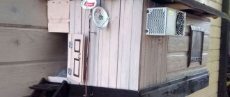
... even if my street cats have a “normal” antenna on their house, what can you do without an antenna?!
The wire is not all finished yet, now we’ll assemble something!
In the places described, I previously used home-made broadband log-periodic antennas, probably since the “beginning of perestroika.” They worked well in analog and not only on UHF, but “for some reason, digital was too tough for them.” I didn’t really delve into the essence of the reasons, I removed them and began to think about what to replace them with. Here is one of them, waiting for a place in the trash
A little history
In the early 60s of the last century, our compatriot Kharchenko K.P. developed a simple flat zigzag antenna with good characteristics.
Copyright certificate No. 138277 for an invention called “Band directional antenna” was issued to Konstantin Pavlovich Kharchenko in 1961 (according to his application dated June 16, 1960). In the same year, materials were published in the magazine “Radio” for repetition by radio amateurs.
The antenna is not critical to materials and dimensions during manufacturing, has a simple good match with the reduction cable, and it successfully combines multiple elements of a common-mode antenna array with a single feed point.
Outdoor antennas for Digital TV. Active or passive model
It would seem that an outdoor TV antenna for digital TV with an amplifier is better than just a design for linear reception. In practice, things are somewhat more complicated. Active models have a number of disadvantages.
- The amplifier is often unique. If it fails, and the antenna has not been produced for a long time, it may not be found on sale.
- There is no lightning protection within a single set of equipment.
- An amplifier installed on an outdoor antenna is subject to changes in temperature and humidity. If the protective housing is damaged (birds love to peck at bright plastic, and it itself crumbles under the influence of ultraviolet radiation), water may enter during rain.
- With a good basic signal level, overamplification may occur, then both the TV and the receiver will refuse to show the picture.
An active antenna is bought by people who do not have knowledge of switching electrical circuits and generally connecting any intermediate equipment. For them, a ready-made kit from which a cable goes to the TV is an ideal option. More rational people choose a passive model and, if necessary, use it in hybrid mode.
Equipment without an amplifier is practical and reliable. An outdoor antenna for passive digital television has a sufficiently high base gain for stable signal reception even at a considerable distance from the broadcaster. If necessary, additional equipment can be connected to it. It is an amplifier and lightning protection device. In this case, the owner receives:
- full maintainability, if desired, you can replace the amplifier with any model you like;
- all electronic equipment is located in the house;
- you can organize any complex protection against thunderstorms and interference;
- conditions for adjusting and configuring electronic equipment are improved.
Important! Among other things, it is easy to buy high-quality external amplifiers for a passive antenna. They are much higher class than similar devices on the active system. This immediately increases the level of reception and the owner’s enjoyment of his favorite TV shows.
Theory and calculations
The described antenna, in theory, has a horizontal “figure-of-eight” radiation pattern and a relatively high gain, which can be further increased by using a reflector/reflector.
To obtain maximum gain on all channels, it is necessary to make an antenna approximately in the middle of the range between the multiplexes used.
Finding (for calculations) the frequencies of multiplexes used in your region is easy,
for example, a request like “dvb-t2 channel frequencies” + “Krasnodar”
I found something like this:
The middle, between “my” two multiplexes, is 700 MHz - we will calculate the antenna at this frequency.
As a basis for calculating the dimensions of the antenna, we take the drawing of its author
Calculate the wavelength: λ = 300 / f [m]
300/700 = 0.428m, approximately 43cm length of each side of the rhombus
λ/4
=43/4= 10.75
The total length of the material we need (11cm*8=88cm) is less than a meter. The distance between the reduction contacts, where we will solder the cable, is 10-12mm (the standard value for this antenna for frequencies below 900 MHz).
I will make a simple antenna, without a reflector, however, to further increase the gain of this antenna, it is quite possible to install it behind it
for example, from a metal mesh/grill, foil material or simply a metal plate. Its dimensions should be approximately 20 percent larger than the dimensions of the antenna and it should be located at a distance of ƛmax/7. For my case: wavelength (channel 39) 300/618, it turns out...49/7= that is, about 7cm
For those who are too lazy to do the calculations themselves
— you can use an online calculator, the results will differ only slightly from those I received. Here, for example, this one - here you immediately enter the frequencies of two multiplexes and get the dimensions of the antenna (without a reflector) Or another option, with a reflector - I really want to note that in the second option a slightly different calculation option is used, different from the author’s. An antenna with angles other than 90° is assumed and the reflector distance is calculated as λ/8
To make the antenna sheet, it is recommended to use aluminum or copper (copper is easily soldered) with a diameter of 3 mm and higher - the larger the diameter, the more broadband the antenna is. You can use tubes; the thickness of the walls is not important, since only the surface of the material is used (in fact, you can wrap any dielectric with foil to obtain the required material). However, in my opinion, the easiest way is to buy a meter of large-gauge copper wire at an electrical supply store.
How to calculate an antenna for digital television
I had to make a choice between technical characteristics such as gain and permissible bandwidth. Based on past experience, I immediately began to analyze log-periodic models and the wave channel.
I found an interesting option: the Turkin antenna. I began to get acquainted with its features and came across an optimized, modified version.
Turkin design
In 2000, the editors of Radio magazine in No. 11 published an article by N Turkin about an improved long-range reception antenna of the wave channel type. It uses wire rings (copper or aluminum with a diameter of about 2÷5 mm) as active vibrators and passive elements.
The author noted that this design has an increased signal gain, is more broadband, but requires precise settings. It includes:
- dielectric rod on which all parts are mounted;
- passive elements (directors D1÷D3 with reflector R);
- vibrators V1, V2;
- matching device - a ferrite ring placed on the cable near the connection to the vibrators.
The antenna design shown in the picture operates in horizontal polarization.
The distances between the rings and the length of their circles are presented in the table by formulas for the dependences on the signal wavelength λ.
| Distances L | L1 | L2 | L3 | LV | LR | |
| Formula | 0.06λ | 0.12λ | 0.23λ | 0.125λ | 0.2λ | |
| Circumference | D1 | D2 | D3 | V1 | V2 | R |
| Formula | 0.95λ | 0.94λ | 0.93λ | 0.98λ | 1.02λ | 1.08λ |
Optimized calculation
This antenna was tested and improved by V Polyakov. He used the computer simulation program MMANA, popular among radio amateurs. The results of his work are described in Radio No. 1, 2002.
The result is an optimized design with improved bandwidth characteristics and radiation pattern.
The refined conversion formulas for each size are shown directly in the picture. The connection of active vibrators is made on the basis of the famous Swiss square: the rings have cuts at the bottom and are connected to each other crosswise.
Antenna assembly
Let's remove the insulation from a piece of wire one meter long.
I got a wire with a diameter of 4.5mm
The tools you will need are a vice and a hammer. Measure approximately 11cm each and bend at an angle of 90°
The end result is to get such a “geometric” figure
We cut off the excess and solder the ends. It should look something like this...
Solder the cable as shown in the photo.
We lay the cable along one side of the square and secure it with clamps. This arrangement of the cable is necessary for its coordination (there are different opinions, not everyone agrees with this statement).
When using a reflector, the antenna sheet at the extreme points of the squares can also be secured using metal stands, for example, soldered onto the remains of the same copper wire - there are points with zero potential (highlighted in green). In other places, fastening is allowed only through a dielectric.
Do-it-yourself digital antenna for a summer residence. Antenna manufacturing
If we calculate the entire length, we will end up with a value of 112 centimeters. Cut the wire or any other material that you plan to use, take a ruler and pliers, and begin to bend the structure. The angle should be 90 degrees. If the sides do not match in length, it’s okay, a small error is acceptable.
Initial data for making an antenna for digital TV:
- The first element is 13 centimeters and 1 centimeter per loop, by the way, it can be bent right away.
- Two elements of 14 centimeters each.
- Two are 13 centimeters each, but there must be a turn in the opposite direction; here a bend is created to another square.
- Two more sections of 14 centimeters each.
- The last one is identical to the first one.
The antenna frame for digital TV is ready. If you did everything correctly, then between the 2 halves there is a gap of several centimeters in the middle. Naturally, there may be minor differences. After this, the loops and bend areas must be cleaned until no metal is visible. Processing is carried out with fine-grain sandpaper. We connect the loops and crimp them with pliers to fix their position.
The design itself is ready, but in order for the antenna made for T2 to function correctly, the cable must be processed. We start with double-sided stripping of the wire. One edge will connect directly to the antenna. You need to strip the cable in this area so that the cord sticks out about two centimeters. If you get a little more, you can simply cut off the rest later.
We twist the screen and cable braid into a bundle, as a result we get 2 conductors - a central core and a twisted element of several braided wires. All this needs to be tinned.
Using a soldering station, solder the plug to the second edge of the cable. A centimeter length is quite enough, small errors are acceptable. According to the principle described earlier, you need to make a pair of conductors and tin them.
The plug is placed in those areas where soldering will be carried out in the future; first wipe it with alcohol or a special solvent. Then, using a file or emery, we clean it. Place the plastic plug element onto the cord. Now start soldering. Attach a core to the central entrance, and a multi-core braid to the side entrance. Crimp the grip around the insulation.
Screw on the plastic tip; some experts even fill it with glue or a special sealant to strengthen the fixation. While the fixing base is still wet, quickly assemble the plug by screwing on the plastic part, and then remove excess glue or sealant. As a result, it will be possible to maximize the service life of the plug. The homemade product has been created, it's time to connect it.
Tests
And finally, a performance check and a rough
assessment of the quality of the resulting antenna.
In fact, everything is simple with the test - turn it on, it works! And to evaluate whether the game was “worth the candle,” let’s compare the parameters of the received signal from the manufactured antenna with the one I’m already using at the dacha, with a declared gain of 11dBi
The antenna is installed in the attic of a country house, at a distance of approximately 16 km from the tower.
Signal level: factory stationary antenna on the left / homemade on the right
At first glance, the difference is only 1% (95 versus 94) - but this is not a completely correct comparison, since my external antenna is connected through a splitter, which further weakens the signal.
Antennas for Digital TV at the dacha wave channel. Based on received signals
Analog
TV broadcasting in the outdated analog format will stop in the coming years, but for now it is still relevant. Considering that many people have old televisions in their dachas, many gardeners receive an analogue television signal. To receive digital TV, they need either a special set-top box for the TV, or a replacement for the TV itself.
To receive analog TV programs you need a meter range antenna (MV antenna). As a rule, these are quite large outdoor antennas or indoor ones with long “mustaches”.
The MV signal travels over fairly long distances, so in areas remote from transmission towers it happens that there is practically no other alternative other than the meter range.
Digital
A digital TV antenna is designed to receive digital TV in the UHF range. In another way it is also called a DVB-T2 antenna. This option is suitable for you if your dacha falls within the DTV broadcast zone, and your TV also supports receiving a signal in digital format, or you have a special set-top box for your TV.
Read in my article what digital TV broadcasting is and whether your site falls within the DTV broadcast zone. There you will also find answers to some other questions about receiving “digits” at the dacha.
UHF antennas are usually quite compact and, due to their size, are somewhat cheaper than UHF antennas.
Combined
Quite often, manufacturers produce combined versions of antennas for receiving both meter and decimeter signals (VHF/UHF antennas). They are simply a symbiosis of two separate antennas in one housing.
For example, I have such a combined antenna at my dacha and it is connected to two TVs: one TV shows analog TV, and the other shows digital TV.
Assessing the performance of the antenna
Let's try to make a more correct comparison by connecting through the splitter input.
Well, in addition, for clarity, let’s add the number of participants List of antennas taking part in the comparison:
1. External antenna Funke BM 4551 external long-range,
declared gain, from some sources (bought at Yulmart), up to 16dB
2. There is an old UHF loop antenna, from TV Electronica 313d, I must say, despite its simplicity, it’s a very good antenna, that’s why it’s been preserved
3. I went to the store and bought for comparison in the review one of the cheapest, such as a symmetrical vibrator (100% the most purchased by pensioners, due to the low price).
I will carry out all “measurements” at one point, located as close as possible to the external antenna - its location was experimentally selected based on the maximum signal, so we can say that the conditions are approximately the same
So, we have already seen the signal level from the external antenna at 95% (at the time of current measurements it showed 94%), we take it as a standard. All comparisons are made by connecting antennas to the input on the splitter, to which an external antenna is usually connected.
Loop antenna, from Electronics 82% on 39 multiplex and 66% on 60
Budget with “horns” - 62%/38% (on the verge of losing the broadcast)
Double square - 92% on both multiplexes, about a couple of percent less than the external one
Out of curiosity, I decided to check the work of the reflector, which is easy to make from any metal mesh, plate or even foil... It REALLY works noticeably! The level rose to 96%!, which is even higher than the stationary one, with a declared gain of 11dB.
The most interesting thing is the object that I used as a reflector!
There was no foil in the house; the only thing available with a metal surface of the required size was... a laptop cover (I have a metal case). But the main thing is the result! It’s clear that I’m not going to “tie” the laptop to the antenna, and its amplification is enough for me without a reflector
Antennas for Digital TV in the country. Types of antennas
When choosing an antenna for digital TV, you can encounter a huge number of different configurations and types. In fact, all digital antennas differ in their mounting location and type of signal amplification. Below I will try to explain in detail under what conditions and which antenna is best to choose for your dacha.
Indoor antennas
In another way, this type of antenna is called indoor. It differs from external antennas in its overall dimensions and the ability to be installed on any flat surface. However, in most cases this type is suitable only for use within the city. And even then in close proximity to a television tower. Of course, if your dacha is located not far from the repeater, then in such cases the reception can be reliable.
An indoor antenna, when installed in one room, can provide a stable signal. But this does not mean that the signal will be the same when transferred to another room. The fact is that walls and external obstacles can significantly affect the stability of reception.
Digital antennas for summer cottages installed outside the premises
In other words, these are external antennas. The application of this type of antennas is very extensive. They can be installed both in the countryside and within the city. Installing such an antenna will not cause any problems, but will significantly affect the signal quality.
If you are thinking about which antenna to choose for your dacha, then you should understand that they are divided into several types according to the type of signal amplification.
Passive antennas, due to their modification, receive and amplify the signal. They do not have any components that contribute to additional enhancement. This type has one plus: it does not introduce any noise into the signal. However, its design and capabilities may not be sufficient for stable reception.
Active antennas allow you to receive a stable digital signal not only due to their design, but also using an amplifier chip. The amplifier can be installed both inside the antenna itself and outside it. The amplifier is powered from a regular outlet via a power supply.
Directional active antennas typically have a similar design to conventional active antennas. They differ in overall dimensions and additional elements. So, in a directional antenna for digital television, the central core is quite long, and there are additional “whiskers”. This type of antenna is best suited for receiving a stable, high-quality signal outside the city. For example, at a dacha, quite a distance from the city tower.
When choosing an antenna for your dacha, be sure to consider the distance from the signal source to the receiver. There are situations when, when choosing a fairly powerful antenna, the signal was very distorted. In fact, the best is very often the enemy of the good.
Conclusion:
I can confidently recommend repeating it!
Simple, “cheap and tasty”... One of the simplest, indoor antenna mounts... with ordinary suction cups - if you’re lucky with the direction to the television center
The next antenna "recommended for repetition" is... log periodic
“Crazy hands” were with you. Good luck and good mood to everyone! ☕
One of the fairly common types of antennas is “triple square” loop antennas. Moreover, this applies not only to television reception, but to various types of wireless communications - Wi-Fi, 3G, etc. This is facilitated by the comparative ease of manufacture (can be made from one piece of wire), compactness and at the same time fairly high technical characteristics.
However, with all this, the absolute majority of both our and foreign manufacturers, for some reason, ignore the production of “triple square” or at least “double square” frame antennas. Apparently, this is due to the extra costs and complexity of mass production.
Therefore, both in Soviet times and in modern times, these antennas are made by hand, mainly only by the people themselves.
The only known example of a factory-made “triple square” outdoor UHF antenna is from the oldest:
But at the same time, it was not possible to find any store on the Internet that would sell this outdoor model, perhaps due to the high cost from the manufacturer.
And when I was looking at photos of various “triple square” options on the Internet, I accidentally came across one of the photos of an industrial “triple square” indoor antenna. And as it turned out, it was sold nearby, so it was immediately purchased for 393 rubles.
The Signal 3.0 antenna comes in a small, colorful cardboard box about the size of a book. Covered with protective film:
The packaging shows the antenna assembly itself and icons of the main digital television standards. And on the reverse side - completely similar (the protective film has been removed):
Of course, the inscriptions immediately catch your attention: “ QUALITY ROOM UHF ANTENNA ” and “ TRIPLE SQUARE AGAIN IN RUSSIA!” "
The same on the sides - the main advantages and functions are indicated: And here I will note: - CMT circuit, specifically for receiving digital and/or HD channels. However, unfortunately, it was not possible to understand what the abbreviation SMT means (I’m not even sure whether it’s in Latin or Russian). Perhaps CMT could stand for Cellular Mobile Telephone, i.e. cell phone, and we are talking about filtering interference from GSM (but this is just an assumption).
We open the box and see a package with components:
The description will help you quickly assemble the antenna:
Let's look at the components and start with the base - a plastic stand with square holes for fixing the central post. Dimensions - 168 x 94 mm:
Plastic central post with cable and central frame - active vibrator (square side - 126 mm):
Rear frame - reflector (square side - 154 mm) with a lower plastic spacer:
Front frame - director (square side - 108 mm) also with a plastic spacer:
Based on these dimensions, it can be seen that the antenna was designed, as usual, for the middle of the UHF range (approximately channel 38).
All frames use stainless steel wire with a diameter of 4 mm.
And the last detail is the top plastic spacer for fastening all three frames together:
The coaxial cable is 1.43 m long. A 50 ohm RG174 COAXIAL CABLE is used: which is quite strange, because... Even in the description, but for some unknown reason, a cable with a characteristic impedance of 50 Ohms is used. In passing, I note that some well-known domestic manufacturers also do not hesitate to use a cheaper 50-ohm cable: for example, the Locus L 405.05 also uses RG 174/U.
The central plastic stand is a holder for the active antenna vibrator and contains a passive matching board:
as the equivalent of a half-wave cable loop on a single-sided printed circuit board:
electrical connection diagram: The board used has a fairly large metallized area (43 x 32 mm), which is generally not welcome in antennas and, in particular, in frame antennas: there must be a minimum of conductive surfaces inside and outside the frame, otherwise the characteristics of the antenna will deteriorate.
Let's also disassemble the lower plastic spacer at the reflector - we will see a continuous welded joint of the frame: i.e. As usual, passive elements have a closed frame - closed.
But the front frame (director) is open - open: There is a gap here - an insulator about 1 mm thick. The reasons for this extremely rarely used solution were apparently somehow related to coordination or something else.
Finally, we put everything together and get a “triple square” antenna:
The measured dimensions of the antenna are 168 x 157 x 228 mm.
Measured weight: about 300 g.
The rear view clearly demonstrates the name “triple square”:
Front:
Looking from a certain point, all three frames will practically merge, hiding behind the first.
Side:
The distance between the rear frame and the center frame is 78 mm, and between the center and front frame is 58 mm.
It is interesting to note in the description that “The triple square has low windage,” although this indicator is not relevant for an indoor antenna.
Let me remind you once again about the optimal placement of any indoor antennas, especially with plastic windows, or rather metal-plastic ones, because frames and sashes contain a metal frame that prevents the passage of the signal.
In general, the minimum height of the loop antenna must be at least 0.1 λ, which for the longest wavelength - 21 UHF channels will be 63 mm. For Signal 3.0, the lowest part of the reflector has a height of 67 mm, i.e. kept to a minimum.
With a blind flap - the height of the antenna is, in principle, sufficient for reception:
But the rotating sash will definitely block the view:
Therefore, in any case, it is advisable to place the antenna on some kind of stand, for example, an empty plastic jar or an empty box:
Thereby providing higher level of the received signal.
Also, when receiving with any indoor antennas, you should pay attention to the presence of a special energy-saving coating on the glass on the inside of the double-glazed window (such windows look like mirrors from the street):
or energy-saving thermal film:
Moreover, it is often also especially noted:
- eliminate information leakage via electromagnetic fields
- protection against energy in the radio frequency range (microwave radiation)
All this is achieved due to the presence of metals, which of course interfere with signal reception. And if there is still enough signal for GSM communications (there are towers on almost every high-rise building), then problems with television reception, Wi-Fi, and 3G may arise due to weakening of the signal.
Here, for example, is the city broadcast received by the “Signal 3.0” antenna (let me remind you that the blue pillar on the far right is exactly the GSM signal level - it definitely shouldn’t have any problems with tinting):
For example, ZyXEL loss of efficiency for a Wi-Fi signal:
| Let | Additional Loss (dB) | Effective distance |
| Open space | 0 | 100% |
| Window without tinting (no metallic coating) | 3 | 70% |
| Window with tinting (metallic coating) | 5-8 | 50% |
Of course, UHF frequencies 470 - 862 MHz are lower than Wi-Fi 2.4 GHz, but all this is also worth taking into account.
And you can check this yourself: with the same antenna location, look at the Quality scale - with the window open and closed. If the signal is significantly weakened, it means you have metallized glass or film.
This is why it is so important to choose antennas with a high, inherent gain, and not some simple (but also expensive) ones - only with a single frame and a powerful amplifier: and even up to such models produced by the same manufacturers: What characteristics can we talk about here? One complete sham.
As (Karl Rothammel) noted:
Eine gute Antenne ist der beste Hochfrequenzverstärker.
A good antenna is the best high frequency amplifier.
When choosing a obviously weak one, you shouldn’t hope that a powerful amplifier will fix everything later. On the contrary, it can ruin it, both with a very weak received signal and with a strong signal.
In passing, I note that the issue of metallized films/glasses also concerns reception in a car, so in such cases, car enthusiasts sometimes have to install only external antennas, and let me remind you that horizontal polarization is used for television broadcasting, so car antennas must be able to receive horizontal polarization, and not just try to take on a vertical pin.
As I already noted, for the correct orientation of the antenna it is important to know the direction to the nearest towers. The service will help with this, allowing you to determine the exact direction (azimuth) and distance to the two nearest towers: you need to point the mouse at your house, and everything will be shown, for example:
The black end of the arrow shows exactly where the towers are located.
However, in this specific example, for Ramensky near Moscow, neither Bogatishchevo nor Butovo are towers for Ramensky, because they are low-power, are located at a significant distance and are intended for their regions, but the slightly more distant and powerful Ostankino is exactly provides a confident reception area for Ramensky.
Those. The nearest towers shown by the service are not always yours and provide you with reliable reception. But, for example, if you poke into the neighboring Zhukovsky, it will already show Butovo and the correct Ostankino.
By default, the service opens using the Google Maps background, but it is better to choose the Yandex.Maps option: in this case, settlements and houses are shown in more detail.
And besides this, if the reception is somewhere at the dachas, then you can search directly from the satellite image: and it is better to choose the Hybrid option - this is Scheme + Satellite.
The Locate button will allow you to quickly navigate to your locality: But of course, it does this based on yours, issued by your provider, and the IP does not always correspond even to your region, not to mention a specific city. For example, from Beeline you can get almost any IP address from the area of its presence in our country.
Therefore, it is better to type your village, village, town in the search bar at the top and click Find. If there are several villages with the same name, you can select from the list or simply additionally indicate your district and region.
Reception parameters : loggia of the 7th floor of a residential building, surrounded by urban buildings and high-rise buildings. Near transmitter: 2 kW (area about 45 km) located at a distance of about 15 km. And the long-range transmitter: 5 kW (area about 60 km) - at a distance of about 80 km.
As usual, TENiKS DTR-122 was used as a test receiver. Those who also have set-top boxes with a Novatek processor know that the Quality scale is calculated by programmers in such a way that a stable image appears when approximately 40% of the Quality scale is reached.
With the near transmitter, the Quality scale was about 42%.
And if you take the antenna out at arm's length, it increases to 45-50%, and with a distant transmitter - 64%. For comparison, Delta K131 was immediately connected: near - 55-65%, and with distant - 78-80%.
It is no coincidence that I compare it with the log-periodic Delta K131, because The purpose of purchasing a “triple square” was to increase the signal level even more , but the situation turned out to be the opposite.
Moreover, I subsequently checked it in a variety of buildings, with different transmitters (frequencies), but everywhere it was the same: “triple square” Signal 3.0 always showed the Quality scale 10-12% lower than the log-periodic Delta K131. But it should be the other way around - a “triple square” loop antenna should have greater gain than a log-periodic indoor one.
I already doubted the prefix, so I tried it with the prefix on MStar, but although the scale was distributed differently, the principle did not change: Signal 3.0 showed lower % than Delta K131.
Immediately about what, by the way, those who wanted to repeat this high figure regularly encountered, but, unfortunately, no matter how hard they tried, of course they did not get such significant numbers, and were disappointed, blaming everything on their “crooked” hands during manufacturing and setup.
Therefore, I perceived the characteristics indicated in the description simply as a mistake: And I didn’t expect any records from the “triple square”, but it still had to provide at least 8-9 dBi (compared to 6 dBi for K131), but, to Unfortunately, Signal 3.0 did not provide it.
In general, those characteristics were apparently also taken from some issues of popular literature of the Soviet era, where the “triple square” was assigned up to 14 dBi, but analysis and practice cooled this level to 8-9 dBi.
From the same literature there are other inflated characteristics, and it is also unclear why it is indicated - Maximum input power is 100 W, which is probably determined by the parameters of the RG-174 cable, however, this characteristic is meaningless for an antenna originally declared as a receiving one.
In general, you can clearly see step by step how the radiation pattern changes, starting from a single frame, then adding a reflector at the back, and finally installing a director at the front:
And the same for the vertical plane (in both cases the antenna is shown conditionally):
And, as you can see, the characteristics indicated in the table above:
The sector in the E-plane at the -3 dB level is actually not 60°, but only 76° (the -3 dB level is a red dotted circle) and the Sector in the H-plane at the -3 dB level is not 68°, but only 90 °.
the same applies to SWR and forward/backward ratio - in general, all of the above indicators turned out to be more modest.
To even out the chances, I even took a 75 Ohm coaxial cable from Delta K131, but this did not bring significant results.
In general, I would rate the antenna gain as no more than 6 dBi.
And analyzing the reasons for the absence, if not erroneously hypothetical 14 dBi, but at least obtaining the legal 8-9 dBi (as the usual “triple square” is estimated), I came to the detail that I already mentioned above: If you break the black plastic insulator and connect it together , i.e. make the director frame closed - closed (as is usually always done):
Then we get +1 dB in addition to the gain. As noted above, it is not entirely clear why such a non-standard solution was needed - to make the director’s frame open, i.e. - open.
Accordingly, by making a jumper, the Quality scale indicators increased by 5-10%.
Because the diagram has become narrower , the antenna has become more directional, and therefore the gain has increased (that unfortunate plastic insulator is marked in red):
Accordingly, it also narrowed in the vertical plane:
It can be seen that the Sector in the E-plane decreased from 76° to 72°, and the Sector in the H-plane decreased from 90° to 86°.
Of course, these are not the hypothetical narrow 60° and 68° specified in the Specifications, but they are already better than the original version of the antenna - with an open director.
The Quality scale has increased, but, unfortunately, it has only almost approached the readings of Delta K131. I repeat: it should be the other way around - the log-periodic Delta K131 with its 6 dBi should give a slightly lower level than the “triple square” loop antenna of 8-9 dBi.
But apparently the specific implementation of the antenna design is not always successful, and certain shortcomings weaken a potentially stronger antenna.
While scanning the air with the antenna, I noticed that all lower frequencies (from the beginning of the UHF and below) have a clear reception of UHF signals: But this is a UHF antenna - and there should be a minimum of the UHF range here. For comparison, Delta K131 has:
Trying to understand the reasons, everything converged only on the matching device, let me remind you that the equivalent of a half-wave cable loop, made in printed form, is used: However, usually with loop antennas a balun loop is used in the form of a λ/4-short-circuited bridge: I made a loop from a piece of thick wire, and even I connected the cable with the same 50 Ohm. And once again - broadcast with a previously existing board:
And without a board - with a short-circuited bridge:
Reception in the MV band has become quieter. Of course, a small printed circuit board is much more compact than a long cable, but I liked the end result better.
I note that it was never possible to find out the manufacturer of this model, because... Neither on the packaging, nor in the description, absolutely nothing is said anywhere. There are no barcodes, no details of any kind, or even the country where it was made. But something tells me that orders for its assembly/packaging are placed at one of the many factories somewhere in China.
Positive: compact, the only factory model of the triple square loop antenna, uses plastic spacers, better than a single loop antenna, passive, inexpensive. Negative: erroneously inflated and actually untested indicators, the use of a cable with a characteristic impedance of 50 Ohms rather than 75 Ohms and a length of slightly less than 1.5 m, some shortcomings in the design and actual implementation.
In general, even despite some identified shortcomings, I believe that this version of the antenna, which is of the “triple square” type, can be actively used for reception, especially considering the low price - after all, even the simplest single frames are offered 2-3 times more expensive , but of course without giving 2-3 more gain. Well, if you modify it slightly, the gain can be added a little more.
4.7/5 — (18 votes)
You can ask questions about digital television on the DVBpro forum
Author: Alexander Vorobyov, 10 Oct 2015 | Permanent link to the page:
Double or triple square for weaker signal
The TV antenna is used in villages, dachas and in areas that are located on the border of the coverage area of television towers. The device allows you to receive even a very weak signal. If you do everything correctly, the power of the TV signal will increase noticeably.
A double or triple square has only one drawback - you need to direct the structure to the signal source with maximum accuracy. Therefore, if you do not know where exactly the tower is, difficulties will arise.
The number of frames determines the signal quality. Therefore, if you are outside the coverage area, you don’t have to limit yourself to 2-3 frames, you can make 5. Do not open the antenna with varnish or paint it. This negatively affects the quality of signal reception.
What are the strengths of the design? First of all, the quality of reception. Even if you are far from the repeater, the signal will be clear. However, it will be possible to achieve a positive result only if the user correctly determines the dimensions of the frames and matching device.
Materials
To make an antenna for digital TV yourself, you need to prepare materials that will later be used to make the structure. The antenna is made from metal tubes or wire:
- 1-5 meter channel - copper, brass, aluminum tubes 10-20 millimeters thick;
- 6-12 meter channel channel - copper, brass, aluminum tubes 8-15 millimeters thick;
- decimeter range - copper, brass wire with a thickness of 3 to 5 millimeters.
Double square - 2 frames, which are connected by a pair of arrows (upper and lower). The smallest frame is the so-called vibrator, and the largest is the reflector. A device with three frames will have a higher TV signal gain. The third square is usually called the director.
Instructions for creating a T2 antenna:
- The top arrow (made of metal) must connect the middles of all frames.
- The lower boom is made using electrically insulating materials: wood, textolite.
- Arrange all the frames so that their centers are on the same line.
- The direct line should be sent to the repeater.
- The vibrator must be open circuit. Its edges are fixed to a PCB plate.
- If you made frames from metal tubes, then the edges should be flattened and holes should be made in them to fix the lower boom.
- The mast must be made of wood, or at least its upper part.
Size calculation
The calculation of an antenna for digital TV will directly depend on the range - meter or decimeter. The dimensions of the antenna with three frames are characterized by a large distance between the ends of the vibrator. You need to leave more distance - 50 millimeters.
The tables show the dimensions of two-element loop antennas. Meter range:
| Channel numbers | 1 | 2 | 3 | 4 | 5 | 6 | 7 | 8 | 9 | 10 | 11 | 12 |
| IN | 1450 | 1220 | 930 | 840 | 770 | 410 | 390 | 370 | 360 | 345 | 330 | 320 |
| R | 1630 | 1370 | 1050 | 950 | 870 | 460 | 440 | 420 | 405 | 390 | 375 | 360 |
| A | 900 | 760 | 580 | 530 | 480 | 250 | 240 | 230 | 220 | 210 | 210 | 200 |
| Sh | 1500 | 1260 | 970 | 880 | 800 | 430 | 410 | 390 | 375 | 360 | 350 | 335 |
UHF:
| Channels | IN | R | A | Sh |
| 21-26 | 158 | 170 | 91 | 152 |
| 27-32 | 144 | 155 | 83 | 139 |
| 33-40 | 131 | 141 | 75 | 126 |
| 41-49 | 117 | 126 | 68 | 113 |
| 50-60 | 105 | 113 | 60 | 101 |
Size of three-element antennas. Meter range:
| Channel numbers | 1 | 2 | 3 | 4 | 5 | 6 | 7 | 8 | 9 | 10 | 11 | 12 |
| D | 1255 | 1060 | 825 | 750 | 688 | 370 | 354 | 340 | 325 | 312 | 300 | 290 |
| IN | 1485 | 1260 | 975 | 890 | 812 | 438 | 418 | 400 | 385 | 370 | 357 | 345 |
| R | 1810 | 1530 | 1190 | 1080 | 990 | 532 | 510 | 488 | 470 | 450 | 435 | 420 |
| A | 630 | 532 | 412 | 375 | 345 | 185 | 177 | 170 | 163 | 157 | 150 | 145 |
| B | 915 | 775 | 600 | 545 | 500 | 270 | 258 | 246 | 237 | 228 | 220 | 210 |
| Sh | 1500 | 1260 | 970 | 880 | 800 | 430 | 410 | 390 | 375 | 360 | 350 | 335 |
UHF:
| Channels | D | IN | R | A | B | Sh |
| 21-26 | 134 | 158 | 193 | 67 | 98 | 152 |
| 27-32 | 122 | 140 | 176 | 61 | 89 | 139 |
| 33-40 | 110 | 131 | 160 | 55 | 80 | 126 |
| 41-49 | 99 | 117 | 143 | 50 | 72 | 112 |
| 50-60 | 89 | 105 | 129 | 45 | 65 | 102 |
Butterfly antenna
The TV antenna can also be made in the shape of a butterfly. Such a device will be in no way inferior to a decimeter antenna. There is absolutely no need to do everything from scratch. It is much easier to convert a regular grille into a digital one for T2 tuning. To make it yourself, follow these simple instructions:
- Take a small board that will become the basis of the future antenna.
- Cut 8 wires, each 37.5 centimeters long.
- The middle of all wires must be stripped about 2 centimeters.
- Bend the wires until they form a V shape. The distance between the wires should be 7.5 centimeters.
- Cut 2 more wires, each of them should be 22 centimeters long.
- Strip the wires where they will be attached to the antenna base (board).
- Place the screws along the base of the antenna, and then connect the V-shaped elements with two wires.
- Connect the antenna and cable using the special plug.
Every user can create such a device. You don't have to buy anything. The antenna is made from improvised materials.