Another homemade product for those who are bored at home
I needed a couple of antennas for digital, in places with “not the best reception”... I went shopping (this was before self-isolation - if it’s relatively budget-friendly, then it’s complete G. The more expensive one looks decent, but how it works is questionable.
I decided to make something homemade. It was somehow awkward to “twist” an antenna from a piece of cable (although rumor has it it works) - I wanted something simple, but more decent and advanced
In fact, the one I made is not radically more complicated, but somehow more “solid” or something. And the results of its testing were very encouraging, so I decided to sketch out a short description of what and how, in case someone else finds it useful 
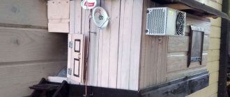
... even if my street cats have a “normal” antenna on their house, what can you do without an antenna?!
The wire is not all finished yet, now we’ll assemble something!
In the places described, I previously used home-made broadband log-periodic antennas, probably since the “beginning of perestroika.” They worked well in analog and not only on UHF, but “for some reason, digital was too tough for them.” I didn’t really delve into the essence of the reasons, I removed them and began to think about what to replace them with. Here is one of them, waiting for a place in the trash
A little history
In the early 60s of the last century, our compatriot Kharchenko K.P. developed a simple flat zigzag antenna with good characteristics.
Copyright certificate No. 138277 for an invention called “Band directional antenna” was issued to Konstantin Pavlovich Kharchenko in 1961 (according to his application dated June 16, 1960). In the same year, materials were published in the magazine “Radio” for repetition by radio amateurs.
The antenna is not critical to materials and dimensions during manufacturing, has a simple good match with the reduction cable, and it successfully combines multiple elements of a common-mode antenna array with a single feed point.
Theory and calculations
The described antenna, in theory, has a horizontal “figure-of-eight” radiation pattern and a relatively high gain, which can be further increased by using a reflector/reflector.
To obtain maximum gain on all channels, it is necessary to make an antenna approximately in the middle of the range between the multiplexes used.
Finding (for calculations) the frequencies of multiplexes used in your region is easy,
for example, a request like “dvb-t2 channel frequencies” + “Krasnodar”
I found something like this:
The middle, between “my” two multiplexes, is 700 MHz - we will calculate the antenna at this frequency.
As a basis for calculating the dimensions of the antenna, we take the drawing of its author
Calculate the wavelength: λ = 300 / f [m]
300/700 = 0.428m, approximately 43cm length of each side of the rhombus
λ/4
=43/4= 10.75
The total length of the material we need (11cm*8=88cm) is less than a meter. The distance between the reduction contacts, where we will solder the cable, is 10-12mm (the standard value for this antenna for frequencies below 900 MHz).
I will make a simple antenna, without a reflector, however, to further increase the gain of this antenna, it is quite possible to install it behind it
for example, from a metal mesh/grill, foil material or simply a metal plate. Its dimensions should be approximately 20 percent larger than the dimensions of the antenna and it should be located at a distance of ƛmax/7. For my case: wavelength (channel 39) 300/618, it turns out...49/7= that is, about 7cm
For those who are too lazy to do the calculations themselves
— you can use an online calculator, the results will differ only slightly from those I received. Here, for example, this one - here you immediately enter the frequencies of two multiplexes and get the dimensions of the antenna (without a reflector) Or another option, with a reflector - I really want to note that in the second option a slightly different calculation option is used, different from the author’s. An antenna with angles other than 90° is assumed and the reflector distance is calculated as λ/8
To make the antenna sheet, it is recommended to use aluminum or copper (copper is easily soldered) with a diameter of 3 mm and higher - the larger the diameter, the more broadband the antenna is. You can use tubes; the thickness of the walls is not important, since only the surface of the material is used (in fact, you can wrap any dielectric with foil to obtain the required material). However, in my opinion, the easiest way is to buy a meter of large-gauge copper wire at an electrical supply store.
Causes of unstable signal
The signal quality of cellular operators depends on several factors:
- Landscape of a specific area.
- The degree of remoteness of devices from operator base stations.
- The quality of the equipment the provider works with.
- Tablet computer or smartphone model.
- Presence of obstacles in the signal path.
- Provider features.
If the signal is consistently bad, this is a reason to send a complaint. But the solution does not have much prospects. Not a single user has yet been able to get an answer to the question of when the signal quality will be improved. A rational solution is to install a 3G, 4G amplifier.
From a technological point of view, users have several options:
- femtocell;
- GSM amplifier;
- antenna for router;
- antenna for modem device.
Femtocell is a compact GSM repeater. It's your own miniature base station. You need to install it in your home. We consider other options further.
Antenna assembly
Let's remove the insulation from a piece of wire one meter long.
I got a wire with a diameter of 4.5mm
The tools you will need are a vice and a hammer. Measure approximately 11cm each and bend at an angle of 90°
The end result is to get such a “geometric” figure
We cut off the excess and solder the ends. It should look something like this...
Solder the cable as shown in the photo.
We lay the cable along one side of the square and secure it with clamps. This arrangement of the cable is necessary for its coordination (there are different opinions, not everyone agrees with this statement).
When using a reflector, the antenna sheet at the extreme points of the squares can also be secured using metal stands, for example, soldered onto the remains of the same copper wire - there are points with zero potential (highlighted in green). In other places, fastening is allowed only through a dielectric.
Maximum 4G
Universal kit for 4G Internet
22000 rub.
Add to cart
Pros:
- Cable length up to 80 meters! The signal and power are supplied over one cable using POE technology.
- Flexible cable.
- Maximum Internet speed. Supports MIMO technology. No other kit will give you higher speed.
- The antenna supports absolutely all frequencies from 700 to 2700 MHz and all 2G, 3G and 4G standards.
- Stable operation at any temperature from -30 to +50 degrees. Factory quality, not basement production from the Mitinsky market
Minuses:
- 1. It is inconvenient to change the SIM card. As a matter of fact, it is not a fact that you will ever need to do this.
- 2. Not yet identified . The price may not seem the cheapest.
A review video of such a device recently appeared:
Tests
And finally, a performance check and a rough
assessment of the quality of the resulting antenna.
In fact, everything is simple with the test - turn it on, it works! And to evaluate whether the game was “worth the candle,” let’s compare the parameters of the received signal from the manufactured antenna with the one I’m already using at the dacha, with a declared gain of 11dBi
The antenna is installed in the attic of a country house, at a distance of approximately 16 km from the tower.
Signal level: factory stationary antenna on the left / homemade on the right
At first glance, the difference is only 1% (95 versus 94) - but this is not a completely correct comparison, since my external antenna is connected through a splitter, which further weakens the signal.
Alternative to 3G/4G Internet
Wi-Fi bridge
If there are residential apartment buildings on the horizon within a radius of up to 10 km, then you can negotiate with the local provider that connects the apartments about a WiFi bridge between the residential complex and your home. 2 antennas are placed towards each other, one on your house, the other on the roof of an apartment building.
In practice, such a connection costs 12 thousand and the tariff is approximately 1000-1500 rubles for 15-30 Mbit/sec. But this is truly unlimited Internet, which, unlike 3G/4G, does not sag in the evening when the load on the network increases. And a good ping of up to 8 ms - for those who like to play tanks and other modern games, this is a luxury in the countryside
WiMax
Wimax is a 4th generation connection. In Russia, this communication standard has not become widespread for a number of reasons.
Some small local companies negotiate with telecom operators to lease their communication channel and place their Wimax equipment on the towers.
And then they connect subscribers by installing appropriate antennas on their roof or facade of the house.
Internet speed of 10-50 Mbit/sec depends on the distance of the tower and the correct installation of the antenna at the subscriber’s home. Ping is about 40 ms. The channel is symmetrical. The cost is about 1000-1500 rubles per month.
Assessing the performance of the antenna
Let's try to make a more correct comparison by connecting through the splitter input.
Well, in addition, for clarity, let’s add the number of participants List of antennas taking part in the comparison:
1. External antenna Funke BM 4551 external long-range,
declared gain, from some sources (bought at Yulmart), up to 16dB
2. There is an old UHF loop antenna, from TV Electronica 313d, I must say, despite its simplicity, it’s a very good antenna, that’s why it’s been preserved
3. I went to the store and bought for comparison in the review one of the cheapest, such as a symmetrical vibrator (100% the most purchased by pensioners, due to the low price).
I will carry out all “measurements” at one point, located as close as possible to the external antenna - its location was experimentally selected based on the maximum signal, so we can say that the conditions are approximately the same
So, we have already seen the signal level from the external antenna at 95% (at the time of current measurements it showed 94%), we take it as a standard. All comparisons are made by connecting antennas to the input on the splitter, to which an external antenna is usually connected.
Loop antenna, from Electronics 82% on 39 multiplex and 66% on 60
Budget with “horns” - 62%/38% (on the verge of losing the broadcast)
Double square - 92% on both multiplexes, about a couple of percent less than the external one
Out of curiosity, I decided to check the work of the reflector, which is easy to make from any metal mesh, plate or even foil... It REALLY works noticeably! The level rose to 96%!, which is even higher than the stationary one, with a declared gain of 11dB.
The most interesting thing is the object that I used as a reflector!
There was no foil in the house; the only thing available with a metal surface of the required size was... a laptop cover (I have a metal case). But the main thing is the result! It’s clear that I’m not going to “tie” the laptop to the antenna, and its amplification is enough for me without a reflector
How does a cell phone booster work?
What is a repeater? This is a device that is used to improve the reception of a cellular device. They are used both in the city and outside it. Works exclusively with the antennas included in the kit - they are connected to it via a cable.
Types and classification of cellular amplifiers
.
Radio frequencies on the territory of the Russian Federation are distributed by the State Commission on Radio Frequencies (SCRF). Each cellular operator has a specific frequency range. It is divided into canal strips, which are narrower sections.
Wideband, single-band and selective.
- Amplifiers with wide channel bandwidths pick up all standard bands, regardless of the telecom operator. Wideband repeaters are the most popular and popular type.
- Single-band devices support only one specific standard band.
- A selective amplifier is a wideband repeater with the advantage of software control. This type is the newest and more expensive. It is possible to configure the signal band manually, but the work is carried out only with one provider, signals from other operators are not perceived.
Analog, digital and optical repeaters
- The most common type of amplifier is analog. They have a simple and reliable design, and for productive work you will need a minimum of settings. On the device body there is a control panel through which the device is controlled.
- Many digital amplifiers are classified as selective. The device is equipped with a remote control function: using a PC, you can change many amplification parameters or control an entire group of repeaters. These models are more expensive, but are perfect for shopping centers, warehouses, etc.
- Professional and most expensive amplifiers are optical. Can transmit high frequency signals via fiber optic cable. The distance between antennas can be up to 20 km. Produced to order and used at large facilities.
How to install and configure a cellular signal booster
The manufacturer will definitely provide instructions for installing the repeater, but let’s pay attention to several recommendations:
- One of the main points will be the installation location. The place where the best signal level will be is the highest point of the building.
- The most important point is to ensure “isolation” between the external and indoor antennas. All this is to prevent the self-excitation mode from starting: the amplifier becomes a generator of noise and interference and interferes with the operation of the tower.
- By keeping the antennas as far apart as possible, you will increase the signal attenuation between the antennas, making it possible to use a more powerful amplifier. The orientation of the indoor antenna should be changed by turning it 90°, which will lead to its polarization from vertical to horizontal. Hence the additional isolation of 10-20 dB. The directions of the antennas (internal and external) must be opposite (180°).
- The next step is to find the location of the nearest station using programs and point the antenna in its direction.
A thick cable should be used if the length is more than 15 m.
What amplifier output power will cover your room?
Output power is the ability of an amplifier to create a coverage area with a stable signal over a certain area.
For a plot of 200-300 sq. m, 100 MW is sufficient (a residential building or a small office). To cover 500-1000 sq. m, the power should be increased to 250-300 mW (country houses or large offices).
Why is self-excitation of an amplifier dangerous and how to avoid it?
Self-excitation occurs on both antennas (internal and external). In the first case, all the bars will appear on the top line of the device, but the connection will be unstable and you will not be able to talk.
Ideal option: the radiation from the repeater should not differ from the radiation from a smartphone. Therefore, we pay attention to the most important installation principles:
- It is worth using a repeater with a small gain and low output power;
- It is necessary to achieve as much isolation as possible between the antennas.
What repeater gain should I choose?
When buying a repeater, it is best to take a spare one, but don’t overdo it!
Important! If the equipment is very powerful for your territory, it can cause severe interference on the BS, for which you will pay an administrative fine.
What else should you consider?
- External antenna gain indicator;
- Internal antenna gain indicator;
- Signal attenuation on the line from the equipment to the external antenna;
- And also network indicators.
To find the gain of the device, you need to add up the antenna gain and subtract from them the signal attenuation on the wires and the network indicators.
There is another way: you need to measure the signal level indoors and, for example, outdoors.
If the signal is weak in the house and strong outside, a repeater with a gain of 65 dB is suitable, if the signals are approximately equal - from 75 dB.
What antennas, cable type and connectors should I use?
External antenna.
Connecting an external antenna is a mandatory step. Be sure to check the compatibility of the antenna and amplifier frequency characteristics, as well as local cellular standards.
Design and directional pattern.
Antenna radiation pattern: circular and directional. The first is usually installed on vehicles and distributes radio waves 360°. This is done because the object will change its position in relation to the operator's towers. Directional antennas have their own individual diagram, as they act as assistants in focusing attention on receiving frequencies from the BS.
- Outdoor antennas vary in design. Outside urban areas, conventional whip antennas with a pie diagram may be suitable. “Wave Channel” is a representative of the most efficient antennas. They are usually used for receptions of the same range.
- Panel antennas are casing-covered arrays that guarantee better signal transmission quality. The gratings of the models vary depending on the configuration - with a large or small gain and operating angle.
- Parabolic antennas will be the most effective. It is a satellite dish that is directed to the BS.
The signal will be weak if the gain is higher. Antennas with a large gain are usually operated at a great distance from the tower.
Indoor (room) antenna.
The internal antenna is designed to broadcast the signal to devices located indoors. The diagrams of such antennas, like external ones, are circular and directional. It is more logical to place circular ones in the middle of the house for uniform signal transmission. Directional ones are mounted on the wall and set a certain distribution range.
Structurally, external and internal antennas are the same, but the external ones are equipped with protection from street conditions and are intended for placement outside.
Cable assemblies
The antennas are connected using cable assemblies. The length should provide sufficient separation of the antennas from each other.
The quality of the signal depends on the quality of the cable and connectors. It is better to choose a cable with a diameter of 7 mm. Depending on the power of the amplifier, the optimal length will be 10-20 m.
We recommend purchasing ready-made kits. They are compiled based on which signal standards you need to amplify. It is also important to remember the repeater gain.
Conclusion:
I can confidently recommend repeating it!
Simple, “cheap and tasty”... One of the simplest, indoor antenna mounts... with ordinary suction cups - if you’re lucky with the direction to the television center
The next antenna "recommended for repetition" is... log periodic
“Crazy hands” were with you. Good luck and good mood to everyone! ☕