A digital cable television transmission system, Digital Video Broadcasting - Cable (DVB-C), founded in February 1994 on the European standard ETS 300 429. Innovations for TV, audio, data and framing structure developed under the auspices of the European Broadcasting Union (EBU) and the European Institute Telecommunication Standardization Standardization (ETSI). Considering what DVB-C is, it should be said that it is part of the DVB standard, which defines the modulation of MPEG-2 frames depending on the type of broadcast.
History of the standard
It consists of types of TV: satellite (DVB-S), cable (DVB-C) and VHF/UHF (DVB-T). The new generation of television signals is based on digital data compression and transmission. This provides high picture quality and better bandwidth utilization than classic analogue color television broadcast standards such as PAL, NTSC and SECAM.
You may be interested in: Designation on a multimeter. How to use a multimeter - detailed instructions for beginners
In January 1995, the DVB project, organized by the EBU, published a set of standards that define a new digital video broadcasting system. Since 1996, DVB has been the technical basis for the implementation of digital TV transmission in the EU in many countries around the world, including Russia. The US has its own terrestrial HDTV standard, which is based on MPEG-2, uses a modem and an audio encoder.
Particular attention in the European classification is paid to the cable standard. What is DVB-C? In answer to this question, it should be noted that modern DVB describes the transmission of digital TV via satellite and cable. It covers the system design and modem for high-bandwidth transmission, as well as several ancillary functions such as teletext, electronic program guides, and conditional access. The system is an ISO MPEG-2 algorithm.
You may be interested in: Designation on a multimeter. How to use a multimeter - detailed instructions for beginners
Building blocks
To understand what DVB-C is, study the elementary circuit. The block diagram of a DVB receiver consists of a cable or antenna:
- Receiver - demodulation - error correction - additional access control and encryption module.
- MPEG demultiplexer.
- MPEG video decoder.
- MPEG audio data decoder.
- Interface.
- RGB/S-Video/PAL/PAL encoder.
- Personal computer or modem, and such DVB-C, which ensures compatible operation.
- TV, VCR.
- Hi-Fi system.
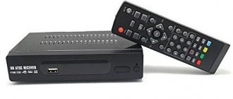
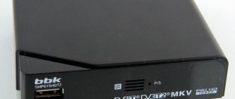
Representatives of the first generation of consumer DVB receivers consisted of a small case containing the receiver and the above MPEG decoder.
The receivers have a data transmission system, interfaces for personal computers and other multimedia systems (EIA-232-E), one or more slots for ISO 7816 chip cards, PCMCIA type 2 connectors for the pay TV access control module, as well as such DVB- C in the TV, which can provide cable connection. Additional interfaces may include digital audio.
MPEG-2 encapsulation
You may be interested in: DIY TV: ideas and options, step-by-step instructions
The DVB project has not defined its own image encoding algorithm, but has chosen a profile (subset) of the international standard ISO/IEC 13818, commonly referred to as MPEG-2 in ETR 154. MPEG-2 is an audio/video compression algorithm optimized for broadcast quality up to the HDTV standard based on discrete cosine transform and motion estimation. For the DVB project, they chose the MPEG-2 core profile at the base layer with a maximum data rate of 15 Mbit/s.
Main level means that up to 720x567 pixels at 25 Hz (TV frequency standard used in Europe) or up to 720x480 pixels at 30 Hz (used in North America) aspect ratios are supported:
- 4:3.
- 16:9.
- 2,21:1.
Basic profile means bidirectional MPEG frames are supported, but no SNR or resolution scalability is used.
ETR 154 has selected certain parameters that must be supported by all DVB receivers.
Video:
- Frame rate is 25 Hz in film mode and field frequency is 50 Hz in video camera mode.
- Aspect ratios 4:3 and 16:9 (2.21:1 optional).
- Receivers must support panning vectors that allow the most relevant portion of a 16:9 image to be displayed on a 4:3 display at the correct aspect ratio.
- Brightness image resolution: 720 x 576, 544 x 567, 480 x 576, 352 x 576,352 x 288.
The MPEG-2 standard also defines the ISO/IEC13818-1 multiplexing system, which allows multiple video and audio streams to be combined into one. DVB uses this multiplexing method to allow many different programs to be implemented with 38 Mbit/s bandwidth.
Features of digital signal level measurement
Perhaps the most understandable parameter for digital TV signals, as well as for analog television, is the parameter characterizing the signal power. But, nevertheless, quite often questions arise related to determining the level of digital channels, so we will pay a little attention to this parameter.
For analog television, the voltage level of the radio signal of the image carrier frequency is measured. For digital TV - “radio signal power in the channel band” (this name is often used in foreign literature) or “the actual voltage level of radio signals with digital modulation in the frequency band of radio signal distribution”, as it is called in the Russian GOST R 52023 - “Networks of cable distribution systems television." In Russia, the parameter is usually measured in dB relative to 1 microvolt (dBµV) for both analog and digital channels.
RF signal power3 for digital channels is measured as the unmodulated signal voltage level that, into a 75 ohm load, dissipates power equivalent to the signal power of the channel being measured.
When measuring signal levels using specialized television meters or universal spectrum analyzers, it should be taken into account that in analog channels the nature of the signal is narrow-band, that is, the main part of the channel power is concentrated in a rather narrow frequency range, and digital channels are characterized by a uniform distribution of power in the channel band. The operation of level meters is based on the principle of a selective voltmeter. That is, a certain frequency band is isolated (filtered) in the radio signal spectrum, and then the voltage of the signal falling within this band is measured.
If, when measuring the level of a narrowband signal, the width of its spectrum is obviously less than the measurement bandwidth4, the level of the measured signal will be constant as the measurement bandwidth changes within the channel. The situation changes when measuring broadband signals, such as digital television radio signals. In this case, the wider the measuring band of the device, the higher the level of the measured voltage. In Fig. Figure 6 shows a spectrogram of a frequency range with several television channels with analog and digital modulation.
The spectrogram was taken using an instrument with a measurement bandwidth of 230 kHz. At first glance, the levels of digital channels are more than 10 dB lower than analogue ones. However, for the analog channel S20, the level (Uan) can be determined from the spectrum as 66 dBµV. And to determine the signal power of the digital channel S23, you must apply the following formula:
U cc = U meas + 10lg(V c /V from ) + K, 5
where Utsk is the required power of the digital channel;
Umeas is the voltage level measured in the center of the channel strip; Vts is the frequency band occupied by the digital channel; Vis - measuring band of the device;
K is a correction factor that compensates for measurement errors6.
Substituting the initial data into the formula, we get:
U S23 = 53 + 10lg(7.5/0.23) + 1 = 69 dBµV.
So in reality the power level of the S23 channel is 3 dB more than the S20.
In level measurement mode, specialized television devices automatically recalculate digital channels taking into account their bandwidth and display their power correctly. But when working in spectrum analyzer mode and when measuring with instruments not designed to work with digital channels, you must remember this feature. This method of measuring channel power at one frequency point gives a fairly accurate result only if the frequency response is sufficiently uniform in the channel band.
Image processing
The first films were shot in the academic 4:3 format. Early TV standards adopted it, maintaining compatibility with cinema. When movie producers switched to a wider format (16:9), home television also adopted this innovation to show quality scenes. Recently, films have begun to be released in an even wider 2.21:1 format.
If a 16:9 aspect ratio image is to be displayed on a 4:3 aspect ratio home theater screen, there are two commonly used methods for adapting the aspect ratio of the image - panning and scanning.
Pan & scan means that the DVB-T T2 C of such a system will show each part of the film in proportion to the ratio 4:3 = 12:9, and the 16:9 picture window will be shown with a smaller side of 9. The remaining 25% of the picture area will be cropped.
DVB-T terrestrial transmission
To understand what DVB T/C is, it is necessary to consider the properties of channel terrestrial transmission systems, for example, the variable signal-to-noise ratio depending on large-scale multipath effects and reflection from neighboring walls of the house. They attenuate certain frequencies, creating a congested spectrum, as well as interference from nearby analogue TV channels and from distant stations in the same band.
You may be interested in: The TV does not turn on, the indicator does not light up: possible causes and solutions to the problem
The selected DVB-T modulation scheme has the following characteristics:
- OFDM (Orthogonal Frequency Control Multiplexing). In this method, the Fourier transform is used to generate a broadcast signal with thousands of mutually orthogonal modulated QAMs. One character carries several kilobits of information. The guard interval allows the echo to pass before the receiver detects the next symbol - 8192 or 2048 carrier frequencies.
- Stability of the modulation scheme against echo.
- Extreme multipath propagation, resulting in much better spectrum utilization while maintaining safe distances between transmitters operating on the same frequencies.
Constellation diagram
Unfortunately, in real life everything is far from ideal. Along the path of delivering a television signal from the source to the end user, there are a great many factors that lead to signal distortion. As a result, to determine the signal quality, you still have to use all possible parameters, including the constellation diagram.
Let's take a closer look at the process of demodulating a digitally modulated signal. After synchronization with the input signal, two values of the vectors I and Q appear at the output of the demodulator block for each symbol.2 A pair of vectors defines a point on the amplitude-phase plane, each of which belongs to one cell that determines a specific symbol value. Ideally, the points fall exactly in the middle of the cells.
Under conditions of noise, the points receive some displacement from the expected position, which is called the output error vector. If the point remains within its cell, the demodulator makes the correct decision, otherwise the symbol is assigned the value of the neighboring cell, which results in an error in the input data stream. Adding white noise to the input signal causes the point to “smear” into a circular spot (Fig. 1). The highest frequency of point hits is in the center, and towards the edge of the circle it decreases. In this case, all spots have approximately the same diameter.
Now consider the case of the simultaneous influence of white and phase noise on signal demodulation. In Fig. Figure 2 shows a constellation diagram for a signal with the addition of parasitic phase modulation (phase jitter), from which it can be seen that phase modulation leads to a greater deviation of points from the center of the cell with increasing vector length. As a result, the probability of an error occurring when decoding points in the corners of the constellation diagram increases sharply. In this case, the MER value does not decrease so much, because the shift for points closer to the center of the diagram is insignificant.
The situation worsens even more if, in addition to phase modulation, there is signal compression that appears when it passes through active devices in the nonlinearity zone of their transfer characteristic. The vertices of long vectors are shifted towards the center of the constellation diagram, as a result of which the probability of errors for these vectors increases even more significantly. Such distortions also do not have a big impact on the MER value.
Below are the results of modeling the three listed situations: measuring a QAM-256 signal in the case of exposure to white noise only, white noise and phase modulation, and white noise simultaneously with signal amplitude compression. Three corresponding constellation diagrams are presented in Fig. 3.
The following diagram (Fig. 4) shows three curves of the BER parameter as the signal-to-noise ratio of the input signal changes. The blue line corresponds to the first case, when the input signal contains only white noise, the purple line corresponds to white noise and phase modulation, and, finally, the green line corresponds to white noise and compression.
Rice. 4. Curves of the dependence of the BER parameter when the signal-to-noise ratio in the input signal changes
It can be seen that at low signal-to-noise values the lines practically coincide, but as the parameter increases they begin to diverge. Finally, the last graph (Fig. 5) shows the dependence of the MER parameter under the same conditions. The graph shows: with a signal-to-noise ratio of 36 dB, when phase modulation is added to the input signal, MER decreases by 0.5 dB, while the BER value deteriorates by several orders of magnitude. The effect of compression is even stronger, although it is barely visible on the constellation diagram.
These are not the only cases of distortion in the original input signal that will result in large BER degradation with little change in MER value. Phase distortions of quadratures, amplitude imbalance of quadrature vectors, etc. lead to similar consequences.
True, the latter types of distortions occur less frequently. The situation with impulse interference is much worse. This kind of signal distortion is not uncommon, since there are a large number of devices that emit a radio signal, which can act as impulse noise for a television signal.
At a sufficiently low repetition rate and short duration, such interference has virtually no effect on the MER value, but can lead to complete degradation of the BER. The situation is complicated by the fact that such interference is difficult to detect. Often a spectrum analyzer does not help either. For example, if the interfering signal is in the channel band and is 20-30 dB less powerful, then it is masked by the useful signal.
Cable Systems Transmitter
Digital Video Broadcasting (DVB) is a set of generally accepted open TV standards. The input signal of the DVB-C transmitter is presented as a sequence of packets with a standard MPEG transport stream. Each packet consists of 288 bytes. It first scrambles to dissipate energy. Next, the packet synchronization is modified. After that it goes through the encoder. 16 bytes are added for protection. The length of an individual packet becomes 304 bytes.
To understand DVB-T2 C S2 what it is in the transmission format, consider the operation of the packets. The modified packets are passed through a depth 12 convolutional interleaver followed by a mapper. It converts packet bytes into two-dimensional QAM symbols with I and Q components.
The most significant two bits of each symbol are then differentially encoded to eliminate the ambiguity introduced by QAM modulation. DVB-C supports different types of QAM: 16-QAM, 32-QAM, 64-QAM, 128-QAM and 256-QAM.
DVB-C receiver
The receiver performs the opposite sequence of operations. The baseband RF signal is level controlled, downconverted, and demodulated. For the last action, carrier and time synchronization are performed. The signal then passes through a matched filter. In cable systems, the channel frequency response is not uniform and can be described as a linear filter. Therefore, the demodulated signal, represented as a sequence of two-dimensional symbols, is adjusted using an equalizer.
The most significant two bits of each symbol are decoded in a differential decoder. The symbols from the signal are then mapped into a sequence of bytes that is passed through the deinterleaver. This is followed by decoding and error correction, and then descrambling. Next, the synchronization bytes are modified. The output signal is a standard MPEG transport stream.
Technical parameters of C-gear
This is the DVB system used to distribute digital TV over cable networks. DVB-C uses the same channels (8, 7 or 6 MHz) that were used to distribute the old analog TV. It is filled with a data container that can transmit uncompressed video, audio, and MPEG-2 data. In this way, digital TV channels can be distributed without the need to stop the distribution of analogue television.
DVB-C uses quadrature amplitude modulation (QAM) for data. Typically 64-QAM is used, but lower level modulation schemes such as 16-QAM and 32-QAM and higher level modulation schemes such as 128-QAM and 256-QAM are also suitable. Their capacity increases when using modulation schemes of a higher level. In this case, the data will be less resistant to noise and interference.
An 8 MHz channel can carry a 38.5 Mbps payload if 64-QAM is used. This is enough for 4-6 television programs. DVB-C is suitable for all 7 MHz and 8 MHz channels in cable networks. In Germany, DVB-C typically uses only 8 MHz channels from 230 MHz to 862 MHz.
BER vs MER
In specialized literature, magazines and on Internet forums, discussions often flare up about the significance of these parameters; You can often come across the opinion that the most important and informative parameter is MER. Proponents of this point of view motivate it by the fact that the dependence of the MER value on the noise level in the channel band is flatter compared to the BER curve, so it is possible to more accurately estimate the margin for stable signal reception. There is, of course, a great deal of truth in this statement. In fact, the MER measurement range typically ranges from 26-27 dB to 38-42 dB and above (for QAM-256 modulation). This allows you to estimate the signal quality margin from the synchronization threshold when the demodulator is just starting to restore the signal at a preBER value of 1E-2...1E-3. In addition, MER tends to be more stable than BER, especially when BER is below 1E-7, due to the averaging time of these values. I will return to this circumstance a little later.
Mux: MERs come in peak and root mean square types. RMS reflects the average value over the measurement period, and peak - the maximum. If the root mean square is measured, then brief disruptions in the pictures at normal MER are quite possible, but switching to measuring the peak value will show these disruptions.
Mux: The lower the modulation dimension of the measured signal, the higher the achievable accuracy of MER measurement. The more constellation points the DAC has to draw, the less time it has for each point. Karlson2k: MER is a good indicator, but not the only one. For receiver
rather, what is important is BER or even PER (BER after Reed-Solomon decoder). Sometimes with the same MER there can be completely different BERs.
Under “normal” conditions, the correlation between MER and BER is quite clear. Indeed, the appearance of BER indicates an approach to the border (which is very thin for a figure - there is still there, a little more and not at all). But it is precisely the border that is important. However, real life is full of conditions when the clarity of the correlation begins to get lost. For example, a frequency shift due to the Doppler effect (relevant for DVB-H) or for some other reasons. Sometimes a failure can be caused by the “features” of the transmitters. Of course, it is difficult to focus on BER when making measurements, especially “fast” ones, and in most cases it is enough to use MER. But for any important measurements you cannot do without BER.
But in practice, the signal level is also important for household receivers. Unfortunately, the difference in the minimum level at which a household receiver picks up a signal reaches 30-35 dB for different models, even from the same manufacturer. Everything is stamped “cheaper”. That is, what to focus on when building
networks - the question is still the same.
New standard
Modern TVs have a new TV standard. However, not all buyers understand the features of DVB T2 C. What is it? It is a standard for digital transmission of signals in broadband cable television systems. The standard defines physical layer techniques, such as error control, modulation, and lower-layer protocols, required for data packaging.
Compared to its predecessor DVB-C, which was originally standardized in 1994, DVB-S2 offers significant advantages in terms of transmission performance, such as spectral efficiency and operational flexibility, variable bandwidth, improved ability to adapt to allocated channel conditions.
DVB-C2 was developed in accordance with the DVB philosophy to use modern technologies and a number of their elements that were not used in the first generation.
The family of DVB transmission systems in second generation standards are harmonized to DVB-C2 (DVB-S2, DVB-T2). The combined PLP and Data Slice multiplexing concepts are an example of such innovation. They ensure that DVB-C2 not only meets the commercial and technical requirements of the European standard, but also provides an optimized solution taking into account operational flexibility and transmission efficiency.
What's better
In all three cases, the broadcast quality is at a high level. The difference between all three broadcast standards lies in the necessary equipment to receive the signal. This means that each type of television broadcasting requires the presence of a special receiver:
- DVB-C requires inserting an access card from the provider into the TV and running a cable. This option is convenient in those apartments where cable TV is already connected. Also, the TV must support this standard. Otherwise, you will need to purchase a tuner. In homes where there is no connection to this type of broadcasting, the standard in question is not suitable.
- DVB-T is terrestrial broadcasting using an analogue antenna. To install such broadcasting, you will need the antenna itself and the tuner itself. Many modern TVs already have built-in tuner functions, in which case there is no need to purchase additional equipment.
- DVB-S broadcasts with high broadcast quality, like the types discussed above. However, to receive such a broadcast you will need a satellite dish and a special decoder.
All of the above standards broadcast channels in Full HD quality. The difference lies in the resources required. Let's take a closer look at each type of broadcast.
DVB-T
Let's figure it out, DVB-T - what is it? As already noted, this is a terrestrial broadcast, which is provided using an antenna and a tuner from the tower. To broadcast it, an antenna is mounted on the street towards the broadcast tower. A cable is laid from it into the apartment and connected to the tuner. And it is directly connected to the TV.
Modern Smarts already include the ability to convert the received signal to the DVB-T standard. And no additional equipment is required. Today an improved broadcast called DVB-T2 is already in use. This broadcasting is carried out using two multiplexers, thanks to which the number of broadcast channels is greater. Digital television differs from the improved standard in the package of channels and signal quality, which supports Full HD and 3D.
DVB-C
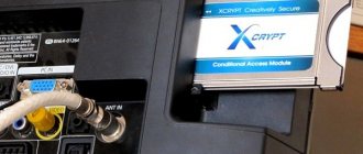
DVB-C is based on a cable connection. This means that in order to broadcast, you need to run a provider cable into your home. You will also need to connect an access card to the CAM module. Almost all TV models have a corresponding connector. If the device does not support this standard, then you will need to purchase a tuner. The quality of the broadcast is high, and the number of broadcast channels is large.
DVB-S
This standard is considered economical, fast and reliable. The signal quality is high. Broadcasting occurs via satellite through a special dish and decoder. The satellite dish is installed on the roof of the house or just outside the window, connected to the decoder using a cable and ultimately connected to the TV. Today, satellite TV is popular due to its high quality and large package of channels.
Comparison of modifications
Differences between DVB-T, DVB-S, DVB-C and DVB-H systems. DVB stands for: Digital Video Broadcasting. The system supports higher resolution and helps increase channel capacity.
DVB-T:
- The short form of digital video broadcasting is terrestrial.
- The transmission modulation scheme is OFDM coded.
- Transmits uncompressed audio and video in MPEG format.
- Data modulation schemes used: QPSK, 16QAM, 64QAM.
- Uses an external RS(204,188) encoder and an internal convolutional encoder.
- Internal and external interleaver are suitable.
- Uses VHF and UHF frequency channels with bandwidths of 6 MHz, 7 MHz and 8 MHz.
DVB-S:
- The short form of digital video broadcasting is satellite.
- Uses MPEG-2 for digital compression and decompression.
- C band is suitable, as well as Ku band frequencies.
- The DBS digital receiver uses FEC techniques to correct errors.
- There are special satellites launched for this purpose.
- Polarization types LHCP and RHCP are used for transmission.
- DVB-S generally requires a smaller antenna.
DVB-C:
- The short form of digital video is broadcast cable.
- Uses MPEG-2 or MPEG-4 compression.
- Data modulation: 16 QAM or 256QAM.
- Uses RS encoder as FEC.
- An alternating module is suitable for the circuit.
- The signal is transmitted via coaxial or fiber optic cable from service providers to subscribers.
- The DVB-C format is such that you can use frequencies from 55.25 to 403.25 MHz.
You may be interested in: Voltage stabilizer "Resanta" ASN 10000: technical specifications, connection instructions
DVB-H:
- The short form of digital video broadcasting is portable device.
- Uses VHF, UHF and L band frequencies.
- Can exist together with the DVB-T system.
- This is one of the standard mobile TV formats.
Ground transmission modernization
DVB-T is a terrestrial video transmission standard created by DVB. It was first used in 1997. Since then, Australia, Europe, parts of Asia, many parts of Africa and Colombia have used it in their broadcasts and television receivers. DVB-T2 is the second version of this standard, introduced in 2008.
Each character that makes up a name has a meaning in DVB-T2:
- DVB is the name of the consortium responsible for creating open digital TV standards.
- T - comes from the terrestrial standard, differentiating it from satellite (DVB-S), cable (DVB-C) and portable broadcasting (DVB-H).
- "2" - second generation.
The goal of DVB-T2 is to achieve better TV retransmission, since the previous DVB-T does not have enough bandwidth to allow the emission of high-resolution channels.
Comparison of technical characteristics of DVB-T and DVB-T2.
| Device, process | DVB-T | DVB-T2 |
| Input interface | TS Simple | Multiple TS and GSE |
| Modulation | OFDM | OFDM |
| Error Correction (FEC) | 1/2, 2/3, 3/4, 5/6, 7/8 | LDPC + BCH1/2, 3/5, 2/3, 3/4, 4/5, 5/6, 6/7, 8/9 |
| Modulation scheme | QPSK, 16QAM, 64QAM | QPSK, 16QAM, 64QAM, 256QAM |
| Guard interval | 1/4, 1/8, 1/16, 1/32 | 1/4, 19/128, 1/8, 19/256, 1/16, 1/32, 1/128 |
| FFT size | 2k, 8k | 1K, 2K, 4K, 8K, 16K, 32K |
General recommendations for assessing the quality of digital channels
Cable operators who have been working with digital television for a long time and have extensive experience advise classifying the state of the cable network on a three-point scale. A rating of three points means that the parameters of the channels in the network meet the requirements for high-quality reception and have sufficient margin for stable, long-term operation. The operator is only required to continue current monitoring. Score two points: the channel parameters also meet the requirements for high-quality reception, but their values do not have sufficient margin to ensure long-term stable operation.
This network condition requires the operator to carry out planned work to identify the source of the problems and decide on methods to restore the network condition to three points. And finally, the third network condition with a score of one point: the parameters of one or more channels do not meet the requirements for high-quality reception, which requires immediate action from the operator to repair or configure the network to raise it to the second or third level. To evaluate each channel, it is necessary to measure all parameters at the subscriber tap. The rating is assigned in accordance with the following conditions.
Score 3 points (all four conditions are met): Channel level: corresponds to the calculated level for a given network point, taking into account the unevenness and the accepted difference between the levels of analogue and digital channels.
MER: no less than 36 dB for QAM-256 modulation and 28 dB for QAM-64 modulation.
PreBER does not exceed 1E7. PostBER: does not exceed 1E9.
Score 2 points (all four conditions are met): Channel level: corresponds to the calculated level for a given network point, taking into account the unevenness and the accepted difference between the levels of analog and digital channels.
MER: Ranges from 34 to 36 dB for QAM256 modulation and 26 to 28 dB for QAM64 modulation.
PreBER: does not exceed 1E6. PostBER: does not exceed 1E9.
Score 1 point (at least one condition is met):
Channel level: does not correspond to the calculated level for a given network point, taking into account the unevenness and the accepted difference between the levels of analog and digital channels.
MER: Less than 34 dB for QAM-256 modulation and less than 26 dB for QAM-64 modulation.
PreBER: value greater than 1E6. PostBER: value greater than 1E-9.
If it is possible to control the constellation diagram, it is necessary to add one more condition. To score “3”, the shape of the constellation diagram should not contain pronounced phase distortions, quadrature imbalance and distortions such as signal compression. If such distortions are present, the measured channel should be given a score of no more than two points.
When indicating the parameter values, I proceeded from the assumption that they were measured correctly, within the measurement error of the device. But under certain conditions, the measured values may fall outside the error limits. In this case, the channel may be assigned a rating that does not correspond to reality.
This method of assessing quality is, of course, not absolute and the only correct one. Each operator can choose the limits of parameter values for assessing signal quality in accordance with the characteristics of a specific network and individual channels; In this case, you should adhere to the general approach to the method of checking the network status.
——
1 The physical meaning of this parameter and the formula for calculating its root-mean-square value are discussed in the articles in the series “Digital cable TV. Part 2. Composition of the headend, calculation of the rebroadcast stream”, “TeleSputnik”, November 2007 and “Digital cable TV. Part 4. DVB signal in the distribution network. The use of alternative standards”, January 2008 (editor’s note).
2 I= A cosφ, and Q = A sinφ where A is the amplitude of the QAM symbol, and φ is the phase of the symbol.
3 This refers to the power characteristic, which in television is usually used as the equivalent voltage of an unmodulated signal, which is equal in power to the television signal. Although the article uses the term “digital channel power,” it actually means the voltage of this equivalent signal (author’s note).
4 The measurement bandwidth is determined by the bandwidth of the measuring filter (editor's note).
5 This is how this formula looks in GOST R 52023 (author’s note).
6 The coefficient depends mainly on the detector parameters (detector type and its time constants) and the rectangularity of the measuring filter. It is determined empirically and, as a rule, is 13 dB (author's note).
Andrey Konorev,
Leading Engineer at Planar LLC
Using a computer
Watching cable TV on your computer is now easier thanks to the creation of PC TV tuners and TV software with DVB-T2 C. What is it? For many viewers who understand electronics, this is clear from the simple operating diagram. Cable TV tuners or TV cards work the same way as a standard TV antenna.
The equipment receives broadcast television signals, which are read by a computer to create live television production. To understand what DVB-C support is, consider the basic algorithm for connecting to a PC:
- Disconnect the power cord attached to the back of the computer unit from the electrical outlet. Unscrew the screws on the left side of the PC using a screwdriver. Remove the side panel.
- Locate the peripheral interface component or PCIe slot on the motherboard. Carefully insert the cable TV tuner card into the slot. Secure this position with a screw.
- Close the PC case.
- Connect the audio and video cables supplied with the DVB-C PC tuner to the PC.
- Connect one end of the cable to the PC tuner unit, and the other is inserted into the colored connectors on the back panel of the computer case.
- Match the corresponding colors with multi-colored rosettes. Many people are trying to figure out what a DVB-C digital tuner is. This can be clarified from the technical documentation supplied with the model.
- Install drivers for the TV tuner card.
- Click the “Start” button on the PC by first right-clicking “My Computer” and selecting “Properties”, “Device Manager”, and then clicking “Multimedia Controller” from the list.
- Right-click and select “Install Driver”.
- Insert the installation disc supplied with the TV tuner, install the program and restart the computer. Use software to watch cable television on a PC.
Ten years ago, not all TV viewers knew about the DVB-C tuner. Only a few could explain what it is. Today, the modern TV format is beginning to be widely used, which allows for a larger number of channels in one multiplex. Therefore, manufacturers of modern smart TVs are interested in introducing it into their devices. The changes are complex and affect many parties. However, experts note that a complete transition to T2 will occur in 2022.
Source
How to choose the right TV
Today, digital TVs on the market offer a huge variety of models from different manufacturers. It is quite difficult for the average user to understand all this magnificence. After all, even outwardly identical devices can contain many differences, which can only be understood by carefully studying the instructions.
You can simplify your task by knowing what rules are adopted for designating models for various brands of TV manufacturers. First of all, we need to determine whether the corresponding model has a built-in DVB-T2 tuner for receiving digital terrestrial television signals.
Let's see what designation is used for this in marking models for different class=”aligncenter” width=”999″ height=”378″[/img]
- LG. The model name of this brand looks like this, for example, LG 50SJ810T (models until 2021) or LG OLED50C8PLA (from 2021). In the first case, the last letter of the marking is important to us; underneath it lies the designation of the built-in digital tuner. The DVB-T2 we need is hidden under the letters T or V. If the last letter is different, then this model does not have a tuner for receiving signals of the required format. In the newest models, starting in 2021, the labeling rules have changed. Here we pay attention to the penultimate letter. Only the letter L indicates the presence of a tuner for our broadcast standard.
- Samsung. The markings of models from this manufacturer look something like this: Samsung QE55Q9FAMUXRU. The presence of a tuner of the format we need is hidden in the designation of the 4th letter or two letters from the end. The presence of the letters AB (B, AU, U), AK (K), AT (T), SB, ST or DK means that this model supports DVB-T2.
- Sony and Panasonic. These manufacturers, unfortunately, do not include information about the presence of a TV tuner in the labeling.
- Philips. Models from this company are marked with type coding 40PFS6401/12. Where the presence of a DVB-T2 tuner is indicated by the 5th letter from the beginning. The letter T or S indicates that the TV supports receiving a signal of this format.