Another homemade product for those who are bored at home
I needed a couple of antennas for digital, in places with “not the best reception”... I went shopping (this was before self-isolation - if it’s relatively budget-friendly, then it’s complete G. The more expensive one looks decent, but how it works is questionable.
I decided to make something homemade. It was somehow awkward to “twist” an antenna from a piece of cable (although rumor has it it works) - I wanted something simple, but more decent and advanced
In fact, the one I made is not radically more complicated, but somehow more “solid” or something. And the results of its testing were very encouraging, so I decided to sketch out a short description of what and how, in case someone else finds it useful 
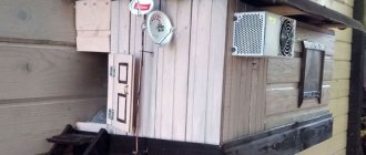
... even if my street cats have a “normal” antenna on their house, what can you do without an antenna?!
The wire is not all finished yet, now we’ll assemble something!
In the places described, I previously used home-made broadband log-periodic antennas, probably since the “beginning of perestroika.” They worked well in analog and not only on UHF, but “for some reason, digital was too tough for them.” I didn’t really delve into the essence of the reasons, I removed them and began to think about what to replace them with. Here is one of them, waiting for a place in the trash
A little history
In the early 60s of the last century, our compatriot Kharchenko K.P. developed a simple flat zigzag antenna with good characteristics.
Copyright certificate No. 138277 for an invention called “Band directional antenna” was issued to Konstantin Pavlovich Kharchenko in 1961 (according to his application dated June 16, 1960). In the same year, materials were published in the magazine “Radio” for repetition by radio amateurs.
The antenna is not critical to materials and dimensions during manufacturing, has a simple good match with the reduction cable, and it successfully combines multiple elements of a common-mode antenna array with a single feed point.
From metal cans
If you can find a couple of straight beer cans made of tin or aluminum at home, then you have the opportunity to quickly assemble a good TV receiver. To do this, you need to take two cans of the largest possible volume, a good result will be achieved with a volume of 1 liter, but if they are not available, then 0.5 liters will do, a screwdriver or screwdriver with a pair of screws, a soldering iron, tape, a television cable, a dielectric base material (in this case, a wooden trempel is used).
The process of making an antenna from metal cans consists of the following steps:
- Rinse and dry the jars to remove any moisture, but be careful not to dent the sides. The smoother the banks, the better the signal will be received by the television receiver.
- Remove the top layer of insulation from the television conductor, approximately 5 - 10 cm, so that only the metal braid remains. Carefully twist it into a kind of conductor. Then strip the solid insulation from the center core to expose bare metal.Fig. 8: Strip the insulation from the cable
Make loops for connection at the terminal of the braid and core.
- Clean the surface of the cans at the wire connection points from paint and varnish to create bare metal. Secure the loops using self-tapping screws - one can from the screen, the second from the core. To improve the signal quality, it is advisable to solder the wires to the banks in addition to connecting with self-tapping screws.
- Place the cans on the trempel arms and secure with tape - the can antenna is ready.Fig. 9: fix on trempel
After installation, you should configure the channels by changing the distance between the banks. The optimal position is selected based on the quality of the signal on the TV. Such an antenna will receive about seven analog TV channels.
Theory and calculations
The described antenna, in theory, has a horizontal “figure-of-eight” radiation pattern and a relatively high gain, which can be further increased by using a reflector/reflector.
To obtain maximum gain on all channels, it is necessary to make an antenna approximately in the middle of the range between the multiplexes used.
Finding (for calculations) the frequencies of multiplexes used in your region is easy,
for example, a request like “dvb-t2 channel frequencies” + “Krasnodar”
I found something like this:
The middle, between “my” two multiplexes, is 700 MHz - we will calculate the antenna at this frequency.
As a basis for calculating the dimensions of the antenna, we take the drawing of its author
Calculate the wavelength: λ = 300 / f [m]
300/700 = 0.428m, approximately 43cm length of each side of the rhombus
λ/4
=43/4= 10.75
The total length of the material we need (11cm*8=88cm) is less than a meter. The distance between the reduction contacts, where we will solder the cable, is 10-12mm (the standard value for this antenna for frequencies below 900 MHz).
I will make a simple antenna, without a reflector, however, to further increase the gain of this antenna, it is quite possible to install it behind it
for example, from a metal mesh/grill, foil material or simply a metal plate. Its dimensions should be approximately 20 percent larger than the dimensions of the antenna and it should be located at a distance of ƛmax/7. For my case: wavelength (channel 39) 300/618, it turns out...49/7= that is, about 7cm
For those who are too lazy to do the calculations themselves
— you can use an online calculator, the results will differ only slightly from those I received. Here, for example, this one - here you immediately enter the frequencies of two multiplexes and get the dimensions of the antenna (without a reflector) Or another option, with a reflector - I really want to note that in the second option a slightly different calculation option is used, different from the author’s. An antenna with angles other than 90° is assumed and the reflector distance is calculated as λ/8
To make the antenna sheet, it is recommended to use aluminum or copper (copper is easily soldered) with a diameter of 3 mm and higher - the larger the diameter, the more broadband the antenna is. You can use tubes; the thickness of the walls is not important, since only the surface of the material is used (in fact, you can wrap any dielectric with foil to obtain the required material). However, in my opinion, the easiest way is to buy a meter of large-gauge copper wire at an electrical supply store.
Antenna designs for digital TV
Antennas for digital TV can be different in design, so their main forms are listed below.
Types of forms
Such antennas are mainly of the log-periodic type. Their design uses several groups of pins of varying lengths. They are direction sensitive, but have a fairly large bandwidth.
They come in the following forms:
- Flat unidirectional. In design, they are similar to a rod on which pins are installed in increasing order of length (small at the end, longer closer to the base). They are very reliable, but they have one drawback - they need to be pointed exactly in the direction of the repeater, because they are capable of receiving a signal from only one direction. They are considered the most affordable.
- Spatial. Their design uses several devices that are placed in different planes. Capable of picking up direct and reflected radio signals at a distance of 50 km from the repeater. The most expensive, but at the same time the most effective.
- Frame. This design consists of a base and conductors bent into a ring. Simple, but less effective outside the range of visibility of the repeater.
Active and passive antennas
Active models are equipped with a signal amplifier and a power supply that operates from a 220V home power supply. With its help, it is possible to achieve reliable TV signal reception in areas remote from the signal source.
Passive models do not use amplifiers, so they pick up the TV signal due to their design and area. They are installed in areas with reliable signal reception.
It is necessary to choose one or another model taking into account the quality of signal coverage specifically in your area. It should be taken into account that it is not advisable to install an antenna with an amplifier close to the signal source, since this is an additional expense. And in areas with poor digital TV coverage, it is pointless to install a passive model, since it will not allow you to achieve the desired result.
Antenna assembly
Let's remove the insulation from a piece of wire one meter long.
I got a wire with a diameter of 4.5mm
The tools you will need are a vice and a hammer. Measure approximately 11cm each and bend at an angle of 90°
The end result is to get such a “geometric” figure
We cut off the excess and solder the ends. It should look something like this...
Solder the cable as shown in the photo.
We lay the cable along one side of the square and secure it with clamps. This arrangement of the cable is necessary for its coordination (there are different opinions, not everyone agrees with this statement).
When using a reflector, the antenna sheet at the extreme points of the squares can also be secured using metal stands, for example, soldered onto the remains of the same copper wire - there are points with zero potential (highlighted in green). In other places, fastening is allowed only through a dielectric.
Calibration
Before starting measurements, you need to make sure that all components of the device are in good working order and the quality of the cables; to do this, we connect the generator and receiver directly with a cable, turn on the generator and measure the frequency response. We get an almost flat graph at 0dB. This means that over the entire frequency range, all the radiated power of the generator reached the receiver.
Connecting the generator directly to the receiver
Let's add an attenuator to the circuit. An almost even signal attenuation of 15dB is visible throughout the entire range.
Connecting the generator through a 15dB attenuator to the receiver
Let's connect the generator to the OUT connector of the coupler, and the receiver to the CPL connector of the coupler. Since there is no load connected to the IN port, all the generated signal must be reflected, and part of it must be branched to the receiver. According to the datasheet for our coupler (ZEDC-15-2B), the Coupling parameter is ~15db, which means we should see a horizontal line at a level of about -30 dB (coupling + attenuator attenuation). But since the operating range of the coupler is limited to 1 GHz, all measurements above this frequency can be considered meaningless. This is clearly visible in the graph; after 1 GHz the readings are chaotic and meaningless. Therefore, we will carry out all further measurements in the operating range of the coupler.
Connecting a tap without load. The limit of the operating range of the coupler is visible.
Since measurement data above 1 GHz, in our case, does not make sense, we will limit the maximum frequency of the generator to the operating values of the coupler. When measuring, we get a straight line.
Limiting the generator range to the operating range of the coupler
In order to visually measure the SWR of antennas, we need to perform a calibration to take the current parameters of the circuit (100% reflection) as a reference point, that is, zero dB. For this purpose, the OSA103 Mini program has a built-in calibration function. Calibration is performed without a connected antenna (load), calibration data is written to a file and is subsequently automatically taken into account when constructing graphs.
Frequency response calibration function in the OSA103 Mini program
Applying the calibration results and running measurements without load, we get a flat graph at 0dB.
Graph after calibration
We measure antennas
Now you can start measuring the antennas. Thanks to calibration, we will see and measure the reduction in reflection after connecting the antenna.
Tests
And finally, a performance check and a rough
assessment of the quality of the resulting antenna.
In fact, everything is simple with the test - turn it on, it works! And to evaluate whether the game was “worth the candle,” let’s compare the parameters of the received signal from the manufactured antenna with the one I’m already using at the dacha, with a declared gain of 11dBi
The antenna is installed in the attic of a country house, at a distance of approximately 16 km from the tower.
Signal level: factory stationary antenna on the left / homemade on the right
At first glance, the difference is only 1% (95 versus 94) - but this is not a completely correct comparison, since my external antenna is connected through a splitter, which further weakens the signal.
How to choose an antenna for your home
To choose the right antenna, you need to know where the signal repeater is located. If it is no more than 15 km away, and there are no obstacles in the form of high-rise buildings in the path of the radio signal, then you can buy and install an outdoor or home passive model. It will be able to receive high-quality digital radio signals without an amplifier.
If your home is located less than 5 km from the signal source, then a compact indoor device will be sufficient. But if the digital television receiver is located on the ground floor of the house, and the buildings standing next to it interfere with the reception of the television signal, then an amplifier may be needed.
When choosing the direction of the antenna, it is necessary to remember that buildings can reflect the radio signal. Therefore, if you cannot achieve a high-quality picture, then you need to estimate the trajectory of radio waves and look for better reception by changing the position of the antenna.
If the repeater is 15 to 50 km from your home, then you can purchase an active indoor model or an outdoor antenna. If this distance is over 50 km, then you need to buy devices with good amplifiers.
To make sure whether the old antenna is compatible with the new TV or set-top box, you need to look at their markings. Using the instructions that come with the device or a search query in the Internet browser of a PC or any mobile device, you need to check whether it is suitable. It is prohibited to check compatibility yourself, because this may result in a short circuit and damage to the set-top box or television receiver.
To increase the quality of TV signal reception, you also need to take into account the condition of the cable. If it has been in use for more than 5 years and there are visible bends on it, then it needs to be replaced. At the same time, experts do not recommend twisting the remaining cable into a ring, or insulating the connection points with electrical tape. This can also affect image quality.
Assessing the performance of the antenna
Let's try to make a more correct comparison by connecting through the splitter input.
Well, in addition, for clarity, let’s add the number of participants List of antennas taking part in the comparison:
1. External antenna Funke BM 4551 external long-range,
declared gain, from some sources (bought at Yulmart), up to 16dB
2. There is an old UHF loop antenna, from TV Electronica 313d, I must say, despite its simplicity, it’s a very good antenna, that’s why it’s been preserved
3. I went to the store and bought for comparison in the review one of the cheapest, such as a symmetrical vibrator (100% the most purchased by pensioners, due to the low price).
I will carry out all “measurements” at one point, located as close as possible to the external antenna - its location was experimentally selected based on the maximum signal, so we can say that the conditions are approximately the same
So, we have already seen the signal level from the external antenna at 95% (at the time of current measurements it showed 94%), we take it as a standard. All comparisons are made by connecting antennas to the input on the splitter, to which an external antenna is usually connected.
Loop antenna, from Electronics 82% on 39 multiplex and 66% on 60
Budget with “horns” - 62%/38% (on the verge of losing the broadcast)
Double square - 92% on both multiplexes, about a couple of percent less than the external one
Out of curiosity, I decided to check the work of the reflector, which is easy to make from any metal mesh, plate or even foil... It REALLY works noticeably! The level rose to 96%!, which is even higher than the stationary one, with a declared gain of 11dB.
The most interesting thing is the object that I used as a reflector!
There was no foil in the house; the only thing available with a metal surface of the required size was... a laptop cover (I have a metal case). But the main thing is the result! It’s clear that I’m not going to “tie” the laptop to the antenna, and its amplification is enough for me without a reflector
Is it possible to use a common house antenna to watch digital TV?
Yes, you can connect to a collective antenna located on the roof of an apartment building. If such a structure is not installed, the residents of the house can send an application to the management company with a request to install such a TV antenna on the roof.
Typically, the antenna complex operates in the all-wave range. But, before connecting, it is recommended to clarify whether it can work in the UHF range. Next, an agreement is concluded with the management company or the provider servicing the complex (most likely with the latter) for the provision of digital television services.
After signing the contract, the TV set-top box without an antenna is paired with a coaxial cable, which is serviced by the provider. After paying the tariff package, the TV will start showing digital television.
Read more: How to connect to a shared antenna to watch digital TV
Conclusion:
I can confidently recommend repeating it!
Simple, “cheap and tasty”... One of the simplest, indoor antenna mounts... with ordinary suction cups - if you’re lucky with the direction to the television center
The next antenna "recommended for repetition" is... log periodic
“Crazy hands” were with you. Good luck and good mood to everyone! ☕
A piece of wire at 433MHz
Often in various devices, such as radio switches, you can see a piece of straight wire as an antenna. I cut a piece of wire equal to a quarter wavelength of 433 MHz (17.3 cm) and tinned the end so that it fits snugly into the SMA Female connector.
The result was strange: such a wire works well at 360 MHz but is useless at 433 MHz.
I started cutting the wire off the end piece by piece and looking at the readings. The dip in the graph began to slowly move to the right, towards 433 MHz. As a result, over a wire length of about 15.5 cm, I managed to get the smallest SWR value of 1.8 at a frequency of 438 MHz. Further shortening of the cable led to an increase in the SWR.
Radio channels in different parts of the frequency spectrum
To clarify further presentation, we will make a technical digression here about the features of various frequency ranges and the associated principles for constructing radio networks. Modern radio communications operate at frequencies of hundreds of megahertz, thousands of megahertz (i.e. gigahertz) and even tens of gigahertz. The radio spectrum is divided into areas dedicated to a variety of applications; radio communication is only one of them. The distribution of spectrum on an international scale is regulated by the relevant international committee, which includes Russia. In Russia it is regulated by the interdepartmental State Committee on Radio Frequencies (SCRF). We'll come back to this later.
Each section of the radio spectrum is cut into channels of the same “width” (for example, 25 kilohertz for cellular telephony). The maximum data rate in a given channel depends only on the width of the channel, and not on the portion of the spectrum in which it is located. It is clear that in the frequency range, say, from 8 gigahertz to 9 gigahertz, there will be 10 times more channels of a certain width than in the range from 800 megahertz to 900 megahertz. Thus, the higher the frequencies, the greater the overall “capacity” of the range in terms of the possibility of simultaneous transmissions: if you imagine the 800-MHz range as a thousand-core cable, then the 8-GHz range will already be a ten-thousand-core cable.
Line of sight and the cellular network principle
One might assume that the colossal capacity of the ultra-high frequency (microwave) part of the radio spectrum could solve all radio communication problems. This is almost true, but there is one purely physical feature of radio waves: the higher the frequency of the wave (i.e., the shorter its length), the smaller the obstacle it can bend. Therefore, say, mobile cellular communications can operate at frequencies no higher than 2 gigahertz: at higher frequencies, communication is already strictly limited to line of sight (almost like a light beam), so communication with a mobile phone will be interrupted like the light from a flashlight when you walk in front of palisade.
At frequencies below 2 GHz, the requirement for line of sight is not so strict: a radio wave can even bend around buildings - but not the thickness of the earth, i.e. cannot “go beyond the horizon.” The limited range of the transmitter by the horizon visible from the height of its antenna makes it possible to organize a cellular network, i.e. such a network in which the same frequency channels can be used repeatedly in non-contiguous territorial areas (“cells”).
Note 1: When people talk about a “cellular phone” or “cellular network,” they usually mean the mobile cellular telephone network. Such networks are typically deployed in accordance with recognized international standards; they occupy part of the ranges around 450 MHz, 800 MHz and 900 MHz, and the latest standard offers a frequency around 1800 MHz (i.e. 1.8 GHz). Cellular mobile telephony is a separate, specifically regulated type of telecommunications activity, and we will not touch upon it further here. The cellular principle of building a network itself is not directly related to mobility - it is simply a way of reusing the same frequencies even within a limited area.
Note 2: The picture would not be complete without mentioning satellite communications. All arguments about the capacity of various frequency ranges remain valid here, only the concept of “horizon” almost disappears, since even a satellite hanging above the equator at a suitable longitude (not in the opposite hemisphere) is visible from the polar regions. It is clear that even a narrowly directed antenna on a satellite produces a “spot” on the earth’s surface measuring hundreds or thousands of kilometers. Therefore, compared to terrestrial radio networks, satellites use the airwaves very uneconomically, without the ability to reuse the same frequencies, as is done in cellular networks. Satellite communications is also a separate subject for consideration, and we will not deal with it here. You just need to keep in mind that a very significant part of the frequency spectrum is occupied by existing satellite communications or reserved for future ones.
Antenna directivity
Radio transmission networks use both narrowly directional antennas and antennas with a wider coverage sector, up to omnidirectional (circular). For a point-to-point connection, two (narrow) directional antennas are used, aimed at each other; This is how, for example, radio relay transmission lines are built, in which the distance between neighboring relay towers can be tens of kilometers. A highly directional antenna focuses the radio beam, increasing its energy density; thus, a transmitter of a given power “shoots” over a greater distance.
Another type of communication will be obtained by using only omnidirectional antennas. In this case, the possibility of connecting everyone with everyone will be achieved. This topology is usually used by small institutional networks deployed over a limited area.
Finally, if we place a base station with an omnidirectional antenna and provide all the subscribers it serves with directional antennas focused on it, we get a point-to-many point topology. If we also connect base stations to each other in a certain hierarchy (either by radio relay lines or simply by point-to-point radio connections, or by cable channels), we will get a whole cellular network. In this case, it will be a fixed cellular network, since a mobile subscriber cannot have a directional antenna.
Note: The mobile cellular network is built on the same principle, but with the use of omnidirectional antennas also for mobile subscribers, who do not interfere with each other, both because they always speak on different channels (or alternating on the same channel), and and because the signal from the mobile device is much weaker than the signal from the base station and can only be correctly received by the base station, but not by another mobile device.
Broadband Signal Technology (BTS)
In order to send a high-power radio signal in the microwave range, you need an expensive transmitter with an amplifier and an expensive large-diameter antenna. In order to receive a low-power signal without interference, you also need an expensive large antenna and an expensive receiver with an amplifier.
This is the case when using a conventional “narrowband” radio signal, when transmission occurs at one specific frequency, or more precisely, in a narrow band of the radio spectrum surrounding this frequency (frequency channel). The picture is further complicated by various mutual interferences between high-power narrowband signals transmitted close to each other or at similar frequencies. In particular, a narrowband signal can simply be jammed (accidentally or intentionally) by a transmitter of sufficient power tuned to the same frequency.
It was this vulnerability to interference from conventional radio signals that led to the development, initially for military applications, of a completely different principle of radio transmission called broadband signal technology, or noise-like signal technology (both versions of the term correspond to the abbreviation WPS). After many years of successful defense use, this technology has found civilian applications, and it is in that capacity that it will be discussed here.
It was found that in addition to its characteristic properties (its own noise immunity and low level of generated interference), this technology turned out to be relatively cheap for mass production. Cost-effectiveness occurs due to the fact that the entire complexity of broadband technology is programmed into several microelectronic components (“chips”), and the cost of microelectronics in mass production is very low. As for the remaining components of broadband devices - microwave electronics, antennas - they are cheaper and simpler than in the usual “narrowband” case, due to the extremely low power of the radio signals used.
The idea of NPS is that a much wider frequency band is used to transmit information than is required for conventional (in a narrow frequency channel) transmission. Two fundamentally different methods for using such a wide frequency band have been developed - the Direct Sequence Spread Spectrum (DSSS) method and the Frequency Hopping Spread Spectrum (FHSS) method. Both of these methods are provided by the 802.11 (Radio-Ethernet) standard.
Direct Sequence Method (DSSS)
Without getting into technical details, the direct sequence method (DSSS) can be thought of as follows. The entire used “wide” frequency band is divided into a certain number of subchannels - according to the 802.11 standard, there are 11 of these channels, and we will count as such in the further description. Each transmitted bit of information is converted, according to a pre-fixed algorithm, into a sequence of 11 bits, and these 11 bits are transmitted simultaneously and in parallel, using all 11 subchannels. When received, the received bit sequence is decoded using the same algorithm as when encoding it. Another receiver-transmitter pair may use a different encoding-decoding algorithm, and there can be a lot of different algorithms.
The first obvious result of using this method is the protection of transmitted information from eavesdropping (“an alien” DSSS receiver uses a different algorithm and will not be able to decode information not from its transmitter). But another property of the described method turned out to be more important. It lies in the fact that thanks to the 11-fold redundancy of transmission, it is possible to get by with a very low signal power (compared to the signal power level using conventional narrowband technology), without increasing the size of the antennas.
In this case, the ratio of the level of the transmitted signal to the noise level (i.e., random or intentional interference) is greatly reduced, so that the transmitted signal is already indistinguishable in the general noise. But thanks to its 11-fold redundancy, the receiving device will still be able to recognize it. It's as if they wrote the same word to us 11 times, and some copies turned out to be written in illegible handwriting, others were half erased or on a burnt piece of paper - but still, in most cases, we will be able to determine what kind of word it is by comparing all 11 copies .
Another extremely useful property of DSSS devices is that, due to the very low power level of their signal, they practically do not interfere with conventional radio devices (narrowband high power), since these latter mistake the broadband signal for noise within acceptable limits. On the other hand, ordinary devices do not interfere with broadband devices, since their high-power signals make “noise” only in their own narrow channel and cannot drown out the entire broadband signal. It’s as if a letter written large with a thin pencil were shaded with a thick felt-tip pen - if the strokes are not in a row, we will be able to read the letter.
As a result, we can say that the use of broadband technologies makes it possible to use the same section of the radio spectrum twice - with conventional narrowband devices and “on top of them” with broadband ones.
Summarizing, we can highlight the following properties of the NPS technology, at least for the direct sequence method:
— Noise immunity.
— Does not interfere with other devices.
— Confidentiality of transmissions.
— Cost-effectiveness in mass production.
— Possibility of reusing the same part of the spectrum.
Frequency Hopping Method (FHSS)
When encoding using the frequency hopping method (FHSS), the entire frequency band allocated for transmissions is divided into a number of subchannels (according to the 802.11 standard, there are 79 of these channels). Each transmitter uses only one of these subchannels at any given moment, regularly jumping from one subchannel to another. The 802.11 standard does not fix the frequency of such jumps - it can be set differently in each country. These jumps occur synchronously at the transmitter and receiver in a pre-fixed pseudo-random sequence known to both; It is clear that without knowing the sequence of switching, it is also impossible to accept the transmission.
Another transmitter-receiver pair will use a different frequency switching sequence, set independently of the first. There can be many such sequences in one frequency band and in one line-of-sight area (in one “cell”). It is clear that as the number of simultaneous transmissions increases, the probability of collisions also increases, when, for example, two transmitters simultaneously jumped to frequency No. 45, each in accordance with its own sequence, and jammed each other.
The frequency hopping method, like the direct sequence method described above, provides confidentiality and some noise immunity to transmissions. Noise immunity is ensured by the fact that if the transmitted packet could not be received on any of the 79 subchannels, the receiver reports this, and the transmission of this packet is repeated on one of the next (in the hopping sequence) subchannels.
On the other hand, since when using the frequency hopping method, in contrast to the direct sequence method, transmission is carried out on each subchannel at a fairly high power (comparable to the power of conventional narrowband transmitters), this method cannot be said to not interfere with other types of transmissions.