A TV is a frequently used device that is found in almost every home. The more the equipment works, the more likely it is to fail. Many problems can arise. But, before taking the TV to a repairman, you need to make sure that the problem exists at all, and if so, what it is. It is quite possible that you can repair your TV yourself at home.
Troubleshooting algorithm
To find the answer to how to repair a TV, you need to understand what the problem is. Identifying faults will help both for independent TV repair and for a service center. In the second case, you will be able to explain to the technician the reason for the breakdown of the television device, which will speed up the process of solving it.
Below is a description of the main malfunctions that occur when the TV breaks down:
- I can't turn off the device. It doesn’t matter: whether it’s a CRT TV or a modern LCD TV, there is only one reason - the fuse has blown. It just acts as different parts in different devices. It is also possible that the diode bridge does not work.
- In both domestic and imported TVs, the potential for which the posistor is responsible may be lost.
- The plasma is broken. This may manifest itself in changes in the color rendering of the television broadcast, differences, interference, and the appearance of light or dark stripes.
- The power cord is broken or the socket is faulty.
If you decide to find the problem yourself, you will first have to clean the internal elements from dust, using a soft brush or vacuum cleaner. Sometimes you can visually determine the location of the malfunction by changing the color of components or their deformation. If such an inspection does not produce results, you will have to look in specific circuits and devices: power supply, picture tube, video amplifier, etc.
Design and features of the MS-994A chassis
Structurally, the chassis consists of a main board, a kinescope board, an “EYE” board (see Table 1) and a teletext module. The last two nodes are installed optionally. The main feature of the new chassis is the use of a multifunctional chip IC501 type TB1238AN from TOSHIBA, containing an amplifier, video detector, audio demodulator, video processor, clock processor and I2C interface circuit. Its use has significantly simplified the chassis circuitry, which, in turn, has led to increased reliability of televisions.
Table 1. Main technical characteristics of LG TVs based on the MS-994A chassis
| Characteristic | Description |
| Screen diagonal, inch | 14, 20, 21 |
| Color television systems | PAL, SECAM, NTSC 4.43 (NTSC 3.58 - from LF input) |
| Television standards | D/K, B/G, I, M |
| Received frequency range, MHz | VHF-L: 46.25…168.25 VHF-H: 172.25…463.25 UHF: 471.25…863.25 |
| Number of memorized programs | 100 |
| Additional functions | EYE (automatic adjustment of image parameters depending on lighting); on/off timer; sleep timer; child lock; switching image format (Standard, Wide, Zoom); “camera” mode (not on all models) |
| Nutrition | AC mains 100…270 V, 50 Hz |
| Power consumption, W | up to 95 |
| Sound | Monophonic |
| Output power of the audio channel, W | 5 |
| Antenna input impedance, Ohm | 75, asymmetrical |
The chassis control system is built on a microcontroller (MC) IC01 type MC37221 from MITSUBISHI, working in tandem with a non-volatile memory chip IC02 type 24C04. To exchange data between chips and transmit commands to the IC501 chip, the MK uses the I2C digital interface.
A special feature of the new chassis is the presence of an interface for a video camera, which allows you to use the TV, in particular, as a monitor for a video surveillance system.
In table Figure 2 shows the parameters of replaceable elements depending on the diagonal of the kinescope screen.
Table 2. Parameters of replaceable elements depending on the diagonal of the kinescope screen
| Position designation | Denominations and types of elements | ||
| Kinescope 14″ | Kinescope 20″ | Kinescope 21″ | |
| FR401, Ohm | 2,4 | 5,4 | 1,4 |
| IC804 | SE110N | SE110N | SE115 |
| TN801 | 163-054F | 163-012С | 163-О12С |
| R303, Ohm | 5,6 | 4,7 | 3,9 |
| R304, Ohm | 5,6 | 4,7 | 3,9 |
| R309, Ohm | 5,1 | 5,1 | 1,2 |
| R311, Ohm | 1,5 | 1.5 | 4,7 |
| R405, Ohm | 82 | 47 | 47 |
| R407, kOhm | 12 | 12 | 10 |
| R410, kOhm | 130 | 100 | 100 |
| R905, Ohm | 390 | 330 | 330 |
| R913, Ohm | 33 | 39 | 27 |
| R915, Ohm | 390 | 330 | 330 |
| R922, Ohm | 390 | 330 | 330 |
| R924, Ohm | 470 | 270 | 270 |
| S402, pf | 180 | 180 | 390 |
| S412, uF | 0,39 | 0,33 | 0,36 |
| S414, pf | 7300 | 7300 | 7300 |
| S902, pf | 330 | 560 | 560 |
| S904, pF | 470 | 330 | 330 |
| S907, pf | 270 | 560 | 560 |
Let's consider the operation of the main chassis components and the audio and video signal paths, as well as the main elements of their processing.
Repair of plasma and LCD TVs
Before you begin repairing LCD or LED TVs, you should carefully read the documentation for the device and study the operating principle of your model.
When repairing plasma TVs yourself, you must take utmost care to avoid deteriorating the condition of the unit. In liquid crystal (LSD) television receivers, the backlight is produced by fluorescent or fluorescent lamps, and in LED televisions, LEDs are used. Repair of imported LCD TVs Samsung, Sharp, Thomson, Panasonic is similar. Therefore, the procedure for their repair is the same, and it is as follows:
- If you cannot turn on the monitor, then the first thing to do is check whether the backlight is supplied with power.
- Unplug the unit from the outlet.
- Regardless of the TV brand, you need to remove the back panel by unscrewing the screws.
- Next, remove the mains power wires from the matrix.
- To check the functionality of the wires, we connect an ordinary 100-watt incandescent lamp to the contacts.
- Modern TVs often have several backlight sources, and therefore it is necessary to check each of them.
- When testing, the matrix is completely removed, the lamp is connected to the contacts, and the power cord is connected to the network.
- If the lamp is on, the wire is working; if not, it is necessary to replace the cable or repair individual threads.
CRT screens
The beginning of repairing an LG TV with your own hands, as well as TV brands such as Panasonic, Samsung, Rubin, Sharp, etc., consists of checking the fuse.
In order to repair televisions with a cathode ray tube, it is necessary to check for the presence of basic faults, and then eliminate them.
Checking the fuse. To do this, unscrew the back panel, under which the board is located. The fuse is connected to the power terminals, which must be switched to the base of a regular lamp and connect the TV to the network. If the lamp goes out, it means the device is functioning properly. If the lamp did not start to burn or, on the contrary, was on all the time, then it is worth concluding that the fuse has blown.
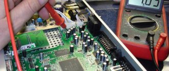
Diode bridge. In the event of this breakdown, repair is possible only after dialing. To do this, you will need a multimeter and a TV passport, which indicates its main characteristics. And then you need to act according to the diagram given in the passport, although if the diode bridge breaks down, it is still better to take it to a service center.
The most difficult problem with CRT television receivers, as a rule, is a faulty posistor. To check it, you need to turn off and on the power circuit and monitor the working lamp. To carry out repairs, you will first need to adjust the network resistance, and then replace the posistor.
Capacitors or transistors have burned out. It is not difficult to detect them, this can even be done visually: if they are swollen or changed color on the board, then there is a problem. In this situation, the damaged part must be replaced.
Sound path
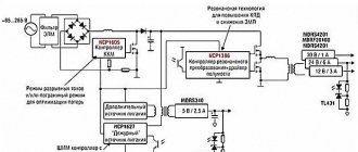
The main part of the audio path is located in the IC501 chip. To isolate audio signals of different standards, use the IC151 switch with filters F151-F154, controlled by MK signals: SO, S1 and M4.5 (pin 38, 39, 14). The IF signal from the output of the video detector (pin 47 of IC501) is fed through buffer Q507 to the inputs of filters F151-F154 connected to switch IC151. Output signal FCZ with pin. 3 IC151 is supplied to the input of the demodulator - pin. 53 IC501. The audio output from the demodulator is amplified and fed to the INT/EXT switch (inside IC501) to select the appropriate signal. External sound signal to pin. 55 IC501 comes with SCART or Cinch connectors. The audio signal source selected by microcontroller IC01 via the I2C interface is removed from the pin. 2 IC501 and is fed to the input of the audio frequency power amplifier (UMZCH) - pin. 5 chips IC601 type TDA7253, which is a single-channel push-pull class AB amplifier with short-circuit protection and a MUTE sound blocking input (pin 3). From its output (the output signal through the coupling capacitor C605 and connector P601 is supplied to the dynamic head. The UMZCH is powered by a 20 V power supply (S-VCC).
Power supply repair
If the LCD TV cannot be turned on and there is no indication at the same time (or it turns on only for a certain time and then turns off on its own), then the problem is most likely in the power supply.
The Samsung TV repair scheme described below can be applied to all LCD TVs:
- Open the back panel of the device using a screwdriver.
- Remove the cover. The power supply will be located on the left side, and the motherboard on the right.
- The power supply board has upper and lower transformers. We begin the check with the last one listed, since it is responsible for the standby mode.
- The transformer we need must produce a voltage of 5 V. To measure the voltage, you need to find a wire. To do this, look at the marking or diagram: the required wire will be marked “5 V”.
- First you need to measure the open circuit. To do this, you need to connect one probe to the found contact, and the second to the diode cathode (located on the radiator). We set it to ring: if there is a sound signal, it means there is no break.
- After this, one probe of the multimeter must be connected to the TV panel, and the second one must be left in the same location. We turn on the screen to the network and begin the process of measuring voltage. If the device shows voltages less than 5 V, it means that the TV is not operating at full power and most likely the capacitor has dried out.
- We resolder the elements that have failed. To do this, you first need to remove the board and disconnect the matrix cable.
- We install the block back and assemble the device. After this the screen should work.
In order to properly assemble the TV and not get confused about where and what part should be located, you can first photograph the location of the parts.
Common TV problems
Modern LCD TVs have become more compact, and their repair has become much easier. Of course, there are breakdowns that are difficult to detect without special diagnostic equipment. But most often there are faults that can be detected even visually, for example, swollen capacitors. In case of such a breakdown, it is enough to unsolder them and replace them with new ones with the same parameters.
All television receivers are identical in design and consist of a power supply unit (PSU), a motherboard and an LCD backlight module (lamp is used) or LED (LED is used). You shouldn’t repair the motherboard yourself, but the power supply and the screen backlight are quite possible.
Can't turn the TV on or off
If the TV cannot be turned on at all, then most likely the cause of the problem should be looked for in the power supply. If there are frequent voltage drops in the network, then it could simply burn out. This may also cause the device to turn off spontaneously. If the model is equipped with special protection, then during voltage surges it will trip and turn off the equipment.
If there is a clear certainty that there are no problems with voltage, then the reason may be the appearance of microcracks on the motherboard.
Read more about why the TV won't turn on.
Poor sound quality
If the sound quality suddenly drops sharply, this is due to a malfunction of the speakers. It is necessary to carry out diagnostics and check that they are connected correctly. All contacts must be in good condition. If no problems are identified during the inspection, then you need to study in detail the functioning of the radio channels.
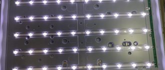
Replacing the backlight
Another reason why the TV screen does not turn on may be a malfunction of the screen backlight lamp. To fix this problem you need to:
- Remove the back panel of the device using a screwdriver.
- The cables should be disconnected from the matrix, and the control panels from the case.
- Remove the housing with electronic boards.
- Unscrew the front panel, then remove the matrix and filters by unclipping the fasteners on the side.
- Turn on the power and hold down a couple of keys to enter the service menu. Thanks to this, the lamps will turn on for a certain time.
- Disconnect the lamp that does not light and replace it with a new one.
- Put all the elements back together.
- Turn on the TV receiver and go to the service menu again. Reset the lamp error counter.
- After this, the unit should function normally.
Microcontroller
MK IC01 performs the function of controlling all chassis components. The operation of the MK is ensured by the quartz resonator X01 (pin 19, 20), the reset circuit IC03 and the non-volatile memory IC02. The purpose of the microcircuit pins is presented in table. 4.
Table 4. Pin assignments of IC01 chip
| Pin number | Signal | Purpose |
| 1 | H-SYNC | Horizontal sync input |
| 2 | V-SYNC | Vertical sync input |
| 3 | LED | LED output |
| 4 | CC/AV-ID | Camera/LF input source identification input |
| 5 | POWER | Power supply control output |
| 6 | ABS | Alarm input |
| 7 | MNT-CTL | Switching sound to SCART (TV/AV) |
| 8 | DEGAUSE | Output for turning on kinescope demagnetization |
| 9 | EYE | Light sensor signal input |
| 10 | IR-IN | Signal input from photodetector |
| 11 | SD-IN | Video signal identification input |
| 12 | TURBO | Tuner tuning mode switch output |
| 13 | TBS-SW | Tuner AGC time constant switch output |
| 14 | 4.5M | Standard M |
| 15 | S-MUTE | Sound blocking output {not used) |
| 16,18,21 | GND | General |
| 17 | FS | Service mode switch input |
| 19 | X-IN | Quartz crystal 8 MHz |
| 20 | X-OUT | Quartz crystal 8 MHz |
| 22 | VCC | Supply voltage +5 V |
| 23 | 0SC2 | Generator output 1 (not used) |
| 24 | 0SC1 | Generator input 1 (not used) |
| 25 | RESET | Reset input |
| 26 | A.F.T. | Tuner fine tuning control input |
| 27 | A.G.C. | AGC voltage input |
| 28 | F8-ID | Blanking pulse input from SCART |
| 29 | KEY1 | Keyboard Scan Input 1 |
| 30 | KEY2 | Input 2 keyboard scan |
| 31 | SDA1 | I2C interface data bus |
| 32 | CCTV-CTL | TV/Camera Mode Switch Output |
| 33 | SCL1 | PC interface synchronization bus |
| 34 | CCTV-ID | CCTV signal identification input |
| 35 | Ym | Switch output "1/2 image brightness" |
| 36 | MELODY | Audio information signal output |
| 37 | 51 | TV standard switch output 1 |
| 38 | SO | Output 2 TV standard switch |
| 39 | FB | OSD blanking pulse output |
| 40-42 | BGR | Video outputs of OSD circuit |
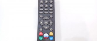
Not working remote control
Before you start repairing your TV yourself, you should check whether the batteries are working from the remote control. If they shrink, they need to be replaced.
Dirty contacts under the buttons. To fix this problem, you need to disassemble the remote control yourself and wipe the contacts, then put the remote control back together.
The quartz emitter is damaged. This could happen if the remote control was dropped. This means that it simply needs to be replaced, since in this situation the emitter cannot be repaired.
Liquid has spilled onto the remote control, or it is completely flooded with water. To fix the problem, you need to disassemble and dry the remote control. If after this the remote control does not start working, then you need to replace it.
No TV signal
If there is no image on the screen, then the reason may be simple - there is no TV signal. This happens because the noise reduction protection is triggered and the device switches to standby mode. You can try to solve the problem yourself and wake up the TV from standby mode. If this does not work, then repairing the TV yourself is not advisable; it is better to take it to a specialist.
Thus, the decision to independently repair a television device must be made after assessing the level of your knowledge and skills in this matter. If you feel unsure of completing the task, it is better to contact the service center specialists.
Typical malfunctions of kinescope equipment and ways to eliminate them
Below is a list of problems that owners of CRT TVs encounter.
Ruby:
- The Rubin TV buzzes loudly when connected - most likely the photodetector needs to be replaced.
- The ruby does not turn on, the indicator does not light up - voltage surges in the transistor.
Horizon:
- The Horizon TV has no blue tint, and the white balance is also disturbed - this is mainly due to a broken resistor.
- There is sound, but no picture - the cause of the problem is poor contact of the power connector on the screen board. It is recommended to use a soldering iron to solder the harness into the board of the Horizon TV.
Knight:
- The screen does not turn on - there is a problem with the power supply.
- A horizontal strip appears on the monitor - repairing a Vityaz TV consists of fixing a problem in the frame scanning chip.