The digital revolution in home theater has an unexpected consequence: audio and video sources are proliferating like the proverbial Australian rabbit. The sight of a dozen electronic boxes in the living room today will not surprise anyone, but in a multi-room installation the number of AV components can approach a hundred. A serious problem arises - how to rationally manage such a vast economy. There are many specialized remote controls on the consumer’s desk, try to find the right one among them! In short, it’s time to turn to specialists for help, for example, from the American company URC. No wonder its name stands for Universal Remote Control, i.e. "universal remote control".
URC is no stranger to knowledge of how to manage a home theater. It has been dealing with this issue for a quarter of a century - from the first day of its existence (founded in 1991). Moreover, the very term “universal remote control”, i.e. UPDU, according to URC representatives, was invented by them. Over the last decade alone, more than 100 million remote controls for home theater, cable television and other purposes have been manufactured and sold under the URC brand. In addition, the company develops remote controls and remote control algorithms for such well-known brands as Denon, Harman Kardon, LG Electronics, McIntosh, Parasound, Rotel, Samsung, Sherwood, etc. Its headquarters are located in Harrison, New York, The development is carried out by highly professional American engineers.
It is noteworthy that if the URC remote control gets between the cushions of the sofa and any button is pressed, there is no risk of premature discharge of its batteries - after 30 seconds the remote control will turn off and will not go into operating mode until the button is released
The entire catalog of URC remote controls can be divided into two categories. The first includes remote controls that correspond to the proprietary Total Control concept, i.e. capable of controlling not only home entertainment systems, but also lighting and climate control. Their name contains the index TRC (Total Remote Control). The second category includes universal remote controls in the usual sense. They have the index TX.
Setting up the watson urc 22b 6n remote control
I. Device programming.
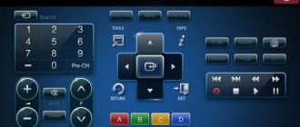
1) Press and hold the SET button. Then press the button of the device you want to control (for example TV1, TV2, CD/HIFI, VCR1, VCR2, CBL, SAT, etc.) 2) As soon as the indicator (LED) lights up, release the pressed buttons. 3) Enter the 3-digit device code. 4) If the entered code is correct, the indicator (LED) will go off. If the entered code is incorrect, the indicator (LED) will blink several times and the remote control will return to programming mode. You must enter the CORRECT device code again! (clause 3)
Note: If you want to exit the programming mode, you must press the device button (eg TV1, TV2, CD/HIFI, VCR1, VCR2, CBL, SAT, etc.). If no key is pressed within 10 seconds, the remote control will automatically exit programming mode.
II. Quick search.
1) Turn on the device to which the remote control is configured. 2) Press and hold the SET button. Then press the button of the device you want to control (for example TV1, TV2, CD/HIFI, VCR1, VCR2, CBL, SAT, etc.) 3) As soon as the indicator (LED) lights up, release the pressed buttons. 4) Press and release the SET button. Now the remote control has entered the fast search mode and the indicator (LED) began to blink quickly. 5) Point the URC22 remote control at the device you want to control and press the POWER or PLAY keys, etc. If the device responds to pressing, go to step 6, if it does not respond, go to step 5 6) Then check other keys, such as [CH+/-], [VOL+/-], that they work. If they do not work, return to step 5 7) Some devices may take a long time to respond to pressing the POWER button. During the search process, you can use the SET button to select the Forward/Backward search direction to find the desired code quickly.
To exit the quick search mode, press the device button (for example TV1, TV2, CD/HIFI, VCR1, VCR2, CBL, SAT, etc.), and the indicator (LED) will go off.
Note: In search mode, in addition to the [POWER] button ([POWER] and [PLAY] in the VCR control unit), all other buttons can be tested. This means that you can check all other buttons without leaving the Quick Search mode. If no key is pressed within 30 seconds, the remote control will automatically exit programming mode.
III. Automatic search.
1) Turn on the device to which the remote control is configured. 2) Press the button of the device you want to control (for example TV1, TV2, CD/HIFI, VCR1, VCR2, CBL, SAT, etc.) 3) Press and hold the SET button. Then press and hold the POWER button for 3 seconds. 4) As soon as the indicator (LED) starts blinking, release the pressed buttons. 5) As soon as the controlled device turns off, immediately press the SET button. 6) Frequency saved. You should check whether the device responds to the URC2 remote control. If not, you should go to step 3
setting up the urc22b remote control
Step one: Selecting a device model
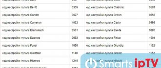
First you need to decide on the device model. On the last pages of the instruction manual there are codes for different manufacturers depending on the class of equipment (TV, VCR, DVD player or stereo system). Having selected the desired device, we find the codes for this device. As a rule, there are several of them. If your device model is not in the list, go to step three.
Step two: Setting up the remote control for the selected device
Having found the code for the device, enter it on the remote control, then simultaneously press the SET and TV keys (or DVB depending on the class of the device). The indicator on the POWER key will light up (if it does not light up, the operation must be repeated), after which we enter the code again, the indicator should go out and the device will be ready for control. If the device does not work, you should try to repeat these operations with a different code suitable for this device.
Step three: If the device is not listed
Automatic search. First you need to turn on the controlled device, so that, for example, one of the television programs is working, then you need to simultaneously press the SET and TV keys (or DVB depending on the class of the device) and hold for several seconds until the POWER key indicator starts flashing. Next, you need to point the remote control at the device and wait for a reaction. If your device reacts, you need to press any key except SET. If you did not have time to react to turning off your device, you can restart the automatic search or proceed to a manual search. Manual search. It is necessary to turn on the controlled device for one of the programs to work, then simultaneously press (short press) the SET and TV (or DVB depending on the class of the device) keys, the POWER key indicator will light up, then briefly press this button (POWER) approximately every second until your device starts to respond. To complete the search, press the SET or TV key.
source
Description
. Manual. I. Programming (option 1) Find the code in the code table. corresponding to your device. 1. Press the SET button and simultaneously one of the TVTXT buttons. TVXT2. VCR1. VCR2. SAT/CBL. CBL/CAT or HIFI/CD/LD until then. until the LED lights up. Then release both buttons. 2. Dial the code (3 digits). 3. Press the POWER button. If the code is correct. the device will turn off. and the remote control will control all functions of the device. If encoding fails. repeat steps 1-3. by typing a different code. indicated in the table. NOTE: All functions must be performed within 10 seconds. II. Quick search (option 2). After that . as you have selected the device code several times. which you want to manage. and it still does not work (for example, the device cannot be controlled by URC22). or you cannot find the correct code in the code list. then you can use the quick search functions. Note. When the remote control entered search mode. you can use the SET button. to switch between “search forward” and “search backward”. 1. Turn on the device. If it's VCR. then there should be a cassette there. 2. Press the SET button and simultaneously one of the T/ТХТ1 buttons. TVTHT2. VCP1. VCR2. SAT/CBL. CBL/SAT or HIFI/CD/LD until the LED lights up. 3. Briefly press SET. Automatic search is enabled and the LED is flashing. 4. Briefly press POWER. At this time, a pulse is emitted from the remote control to turn off the device. 5. In case of device shutdown. turn it on again using its keyboard and check that the basic functions of the remote control are performed correctly 6. In case. if the orders given are executed partially or incorrectly. step 4 should be repeated. 7. To exit the search mode, press the device button. The LED will go off. III. AUTO SEARCH. 1. Turn on the device. which one you need. If it's VCR. then there should be a cassette there. 2. Press and hold SET. At the same time, press POWER for more than 3 seconds. Search works. 3. Press any button to exit. 4. Rules for reading codes:
Analysis of remote control operation protocols
When creating an HTPC, one of the issues is how to manage the shell. I don’t think it’s worth talking about the fact that traditional input devices - a keyboard and a mouse - are not suitable for this task. It is much more convenient to control HTPC in the same way as other consumer electronics - using the remote control. Most often, remote controls from DVD players and similar equipment are used in conjunction with LIRC / WinLIRC, or Windows MCE-compatible remote controls with USB receivers, of which there are plenty in Chinese online stores. Such remote controls emulate a usb-hid keyboard (and sometimes a mouse). These remote controls have a significant drawback - if the motherboard and BIOS do not support power-on and wake-up from USB devices, then using such a remote control you can control the device, turn it off, but will not turn it on. I decided to fight this shortcoming. For my HTPC I chose an Intel D2700MUD motherboard. As it turned out later, it was reckless, since the built-in GMA 3650 video controller, based on PowerVR, is fully supported only in 32-bit Windows, and in Linux the support is very limited - hardware video decoding does not work. But I'm happy with the HTPC running Windows 7 Home Basic. Also, this board cannot wake up on a signal from a USB keyboard. I also already had a remote control (Philips 2422 549 01930), which seemed suitable to me. But WinLIRC worked extremely unstable with it. Apparently some unusual protocol was used.
The first thought was to connect an IR receiver to the Arduino, take the power from the 5VSB bus of the HTPC power supply, and turn the power on (and turn it off) by simulating the short circuit of the pins on the motherboard to which the power button is connected, and transmit the remaining commands through RS-232. But Arduino is too expensive and takes up a lot of space in an already small case. Therefore, I decided to make do with a cheap ATMega8 microcontroller, into which I can install an Arduino bootloader and program it as an Arduino NG.
Parsing the protocol
For Arduino there is a good library for working with infrared remote controls - IRRemote, but it does not work with Arduino NG - there is not enough memory. In addition, I could not get this library to understand my remote control even on the Arduino UNO. As I wrote above, LIRC (and WinLIRC) did not work very well with this remote control - they often missed button presses, sometimes they incorrectly detected the pressed key. The remote control itself worked properly - there were no problems with the “native” DVD player. Searching for information about the protocol for this remote turned up nothing, so I decided to figure it out myself.
For this I needed an oscilloscope, but I didn’t have it on hand, and there was nowhere to get it. But in the case of remote control signals, the linear input of a sound card is quite suitable. I connected the TSOP 31236 infrared receiver to it.
Then, using any audio editor, you can record the input signal and analyze it:
First comes the long message needed to set the automatic gain control level in the receiver. This is followed by pulses of varying lengths. I wrote an intermediate sketch for Arduino that determined the time between pulse edges in microseconds and output them to the terminal via RS232. I loaded the received data into Excel:
When I first started studying the protocol, my main mistake was that I counted the duration of the pulses themselves, but ignored the duration of the intervals between them. After I started counting the intervals between fronts, everything fell into place. As you can see, most pulses of the intervals between edges have durations in the range of 350-550 μs and 700-1000 μs. This means that the values of the transmitted bits are designated as “0” and “1”. The remote control protocol uses a toggle bit. This means that when you press the same key on the remote control several times in succession, one bit (sometimes several) will change in the code. In my case, the toggle bit has an unusual duration - 1200-1400 µs. In addition, the number of fronts in “even” and “odd” parcels is different. Later I came to the conclusion that the interval 1200-1400 μs is the sum of their two bits with the same level, but different durations (400+800). In the code, I designated such a parcel as a sequence of two bits - “01”. Then the number of output bits became constant.
Sketch for Arduino
Then I wrote a sketch that counted the time between input level changes and output the resulting number to the uart. With the help of simple debugging, I achieved stability in the definition of codes, added addition with a mask to ignore the toggle bit (I did not have functions in which it would be useful). Then I hard-coded the function so that when the microcontroller received the “Power” button code, it would press one of the Arduino “digital” pins (12 in my case) to the ground. // I apologize in advance for the Hindu code. I know that it could have been done much more correctly and better, // but for me it was important to solve the problem, and I did not pretend to the elegance of the solution. byte a = 0; // Current input level byte b = 0; // Saved input level byte bc = 0; // Bit counter const boolean dbg=false; // Debug mode =) boolean start=false; // Is the pulse counting started uned int usecs = 0; // Timer 1 - determines the duration of the edges uned int usecs2 = 0; // Timer 2 - defines pauses between sends uned int plen = 0; // Duration of the interval between edges uned int plen2 = 0; // Pause duration between sendings String bits; // Representation of the buffer as ones and zeros, for debugging uned int buffer; // Buffer. Actually, the code of the pressed button is placed here void setup() { // Initialize the digital pin as an output. // Pin 13 has an LED connected on most Arduino boards pinMode(13, OUTPUT); // Ok, let the LED be there. pinMode(12, OUTPUT); // And pin 12 will be connected to the power button connector on the motherboard. digitalWrite(13,HIGH); // Turn on the LED. digitalWrite(12,HIGH); // Set the output to a high level so that the board thinks the contact is open. pinMode(7, INPUT); // We send the signal from the TSOP IR receiver here. Serial.begin(115200); Serial.ln("READY"); usecs = micros(); // Initialize the Hindu timer usecs2 = micros(); } void loop() { a = digitalRead(7); // Read the level value at the input if(a != b) { // The level has changed! Pulse front. start=true; // We consider the pulse counting to have begun. b = a; // Reset the edge detector plen = micros() — usecs; // Measure the elapsed time between the previous and current edges usecs = micros(); // Reset the timer usecs2 = micros(); if (plen<2000) { // filter the start pulse and the duration between pulses if (plen>200 && plen < 620) { // zero bits += “0”; buffer = buffer << 1; buffer = buffer | 0; bc++; } if (plen>620 && plen < 1150) { // unit bits += “1”; buffer = buffer << 1; buffer = buffer | 1; bc++; } if (plen>1150 && plen < 1600) { // toggle bit bits += “01”; buffer = buffer << 2; // Here we shift by two bits! buffer = buffer | 1; bc++; bc++; } if(dbg==true){ Serial.(plen); // if debugging is enabled, display the pulse duration Serial.(";"); } } } else { // If there is no change in the input level in this cycle plen2 = micros() — usecs2; // Determine the duration of the pause if(plen2 > 5000 ) { // IF THE PAUSE IS MORE THAN 5 MILLISECONDS, THIS MEANS THAT THE SENDING HAS ENDED OR HAS NOT STARTED YET usecs2 = micros(); // reset Timer 2 if(start==true){ // If the pulse count was started before, then the key code should have accumulated in the buffer. usecs = micros(); // reset timer 1 while(bc<40){ // align the output. To be honest, I don’t remember why I did it this way, but since I did it, it means it’s necessary. bits += "0"; buffer = buffer << 1; bc++; } buffer = buffer & 1048575; // Using magic-numbers is bad for karma. This is a mask for the toggle bit. Serial.ln(buffer); // OUTPUT THE CODE! if (dbg){ // if debugging is enabled Serial.("bits="); // output the code in the form of ones and zeros Serial.ln(bc); // print the number of bits } digitalWrite(13,LOW); // Flash the LED as a sign, delay(100); // that the code from the remote control was digitalWrite(13,HIGH); // accepted and recognized. switch(buffer){ // Other actions when some buttons are pressed. case 8448: // Power button on my remote control. Serial.ln("POWER"); // Display the POWER message in addition to the button code. Convenient for parsing EventGhost logs. digitalWrite(12,LOW); // Press the pin of the power button on the motherboard to the ground delay(300); // At 300ms digitalWrite(12,HIGH); // And release default: break; } buffer=0; // Reset the buffer bits=""; // Reset the debug line with the bits start=false; // Reset the counting sign bc=0; // Reset the number of bits } } } }
What's next?
And then the EventGhost application reads the codes from the RS-232 port and “pulls the strings” of the well-known XBMC shell. Setting up both is individual and at the same time simple, so it does not deserve attention.
Universal control
For those who do not have an extensive lighting and climate control system at home, the company offers UPDU of the MX line. There are more than a dozen models in it, we will tell you about the main ones.
Programmable universal remote control URC MX-450
The MX-450 is an inexpensive device, but look how much it can do. It has a 2-inch color screen that allows you to select one of 24 video or audio sources, which are indicated by colorful icons. The task of programming such a large number of devices is simplified by the built-in navigator for entering codes into the remote control memory. In addition, a set of such codes can be saved on a computer using special software and restored without problems. The same software allows you to update the remote control software and replenish the library with codes for new devices. The remote works with both IR and RF commands.
Universal programmable remote control URC MX-890
Higher-end devices are represented by the MX-890 remote control. It allows you to control up to 200 components, each with up to 10 menu pages. You can create macros; for example, by pressing one button, close the curtains, turn off the lights and turn on the projector.
Base stations URC MRX-260 and URC MRX-350
Gone are the days when in order to control a certain device you had to have the skills of a sniper - point the remote control directly at it. With the MRX-1, MRF-350 or MRF-260 base station, you have complete control over components in a closed rack or in an adjacent room. The remote control comes with an elegant stand that doubles as a charger.
Universal remote control URC MX-5000
The flagship of the MX-5000 line is capable of operating in bidirectional mode, i.e. Receive information from the managed bean. As a result, the user can, say, look at the cover of an album being played from an iPod (when working in conjunction with the proprietary PSX-2 docking station). Using the Wi-Fi interface, the remote control can be connected to your home network and find out news, sports match results or weather forecasts. The model doesn’t just have a touch screen – the remote control responds to pressing a virtual button with vibration. The MX-5000 is capable of controlling 255 components and works with both infrared and RF signals.