During a thunderstorm, many of us do not unplug household appliances and home electronics. Such negligence is usually very costly. Every year during the summer, information appears about damage caused by lightning.
Electronics and, above all, television and computer equipment are the most sensitive to lightning discharges. Its electronic components are usually configured to operate at low voltages of the order of a few volts, so the appearance of an overvoltage of even a hundred volts will completely destroy them.
Lightning protection for antenna
Antennas installed on our roofs are potential sources of danger to devices inside the building. A direct lightning strike into an antenna mast can result in complete destruction of electronic equipment, including fire of the entire installation. A lightning strike near an antenna does not cause such a sharp effect, but it may well damage parts and circuits inside electrical and TV equipment.
Lightning is an electrical discharge in the atmosphere with a current of 10,000 to 500,000 amperes and a voltage of ten million to a billion volts. A lightning discharge creates an electromagnetic pulse that can destroy electronic equipment within a radius of several kilometers from the point of impact.
However, there is a way to effectively protect all connected playback devices by connecting them to highly sensitive overvoltage protection devices. The methods you will learn about in this article, in particular lightning protection for antennas, will help protect your antenna installation and television equipment. Not only from direct lightning strikes, but also from currents induced in wires and from the introduction of high potentials.
Is grounding always necessary?
Many of us believe that a lightning rod installed on the roof can protect home appliances from lightning. Not everything is right here. A lightning rod really protects a building from a thunderstorm, since it receives and discharges the main lightning strike - its high-voltage discharge - into the ground. But while this happens, an electromagnetic field has time to be generated in the lightning rod, and stray currents are formed that can cause overvoltage in the electrical system of the house and in its power supply line.
Consequences of lightning and electromagnetic pulse
An antenna installed on a building that is not equipped with lightning protection means there is a very high probability of lightning hitting the antenna and the risk of electric shock.
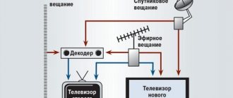
What risks arise during a thunderstorm? For the antenna system and television receivers interacting with it, threats can spread in the following scenarios:
- interaction of the electromagnetic field of a lightning discharge with the loops of wires that exist in the building;
- If the antenna mast is not grounded, then with a direct hit on the antenna, lightning current can penetrate inside the building. Flowing through various types of conductive installations, damage the devices in them;
- a direct lightning strike to the power lines supplying the building;
- a discharge in the immediate vicinity of an object can pose a threat due to the partial influx of lightning electricity through conductors buried in the ground.
You may be interested in: Choosing an over-the-air digital set-top box
The home television system is very vulnerable to power surges during a thunderstorm. Therefore, grounding the antenna is one of the important measures in the complex of its protection, but not the only one.
Regulatory Requirements
Electrical safety requirements that apply to television systems and cable networks can be found in the “Rules for Electrical Installations” (7th ed.), as well as in the instructions RD 34.21.122-87. The measures listed in these basic regulations concern the protection of antenna systems, including satellite ones, from atmospheric phenomena and lightning strikes.
Types of lightning protection
Grounding an antenna, whether in the private sector or in a city high-rise, is a way to “bury” part of the energy in the nearest lawn in the event of a direct lightning strike. The method is natural, but not one hundred percent. There are additional precautions that are successfully used in television networks - the use of special lightning protection devices. See for yourself: a TV that is connected to the mains has an antenna connector. Thus, even an unplugged device can be damaged if a lightning strike hits the antenna. The antenna wire must pass through surge protection elements before being introduced into the building. Coaxial protection modules have been designed specifically for the purpose of lightning protection for coaxial cable.
For coaxial cable lightning protection to be effective, all cables in your home TV network must be protected.
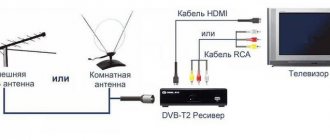
Assembly and connection of the REMO receiver
To receive television channels in digital quality, purchasing an antenna will not be enough; you will need to properly connect and configure it. The device is connected to the TV receiver using a coaxial cable, which is usually supplied with the product. In the case of an external structure, the wire length may be short, and then you will need to buy a new cable.
To connect antennas, it is recommended to choose a product marked 75 Ohm (this figure means the characteristic impedance parameter). Connecting a Ramo antenna must begin with choosing a location and correct orientation. The desired direction is determined by turning the device in one direction or another.
At the same time, you need to monitor the signal level on the TV screen. In the case of digital broadcasting, situations may arise when the first multiplex is received in one position, and in order to view channels from the second package, the location of the structure must be changed. The correct setup and connection of the Remo receiver looks like this:
- If you cannot determine the correct direction, it is recommended to search the Internet for the location of the nearest TV tower. The website rtrs.ru presents an interactive map, which will show not only the location of the repeaters, but also the frequency and channel number for both multiplexes.
- Once the correct direction has been chosen, it is recommended to fix the installation. For fixation, metal ties or special brackets are used.
- The next step is to connect the antenna to the power module.
- Next, you need to connect the coaxial cable to the active component, and connect the power supply to the mains.
- After this, you can start setting up channels. Searching for available channels is performed in two ways: manually or automatically.
- If the user has chosen automatic search, before starting the process, it is recommended to specify digital television instead of analogue broadcasting in the settings.
- All that remains is to wait until the equipment performs a search, and if both multiplexes have been found and the reception signal is stable, you need to save the result.
Manual configuration is necessary in a situation where the reception quality is poor or the subscriber is not sure that he has assembled and configured the receiver correctly:
- The first step is to determine which channels are broadcast by multiplexes in the region where the subscriber is located. You will also need to determine the numbers and frequency for TV channels that broadcast in a given geographic location.
- Now you can go to the main menu of the device and select the “Manual Search” tab on the screen.
- Before specifying the TVC number for one of the multiplexes, it is recommended to indicate the “Digital” broadcast.
- After entering the channel number and frequency, a special scale will appear on the screen demonstrating the quality of reception.
- If the signal is weak, it is necessary to change the position of the receiving device so that the scale level becomes stable and rises to a high level.
- Don't forget to save the result.
To configure TV programs on the second multiplex, proceed in the same way. If the manipulations performed do not bring positive results, you can tune in to another TV tower (when there are several of them in the city). It is also recommended to use an outdoor antenna, installing it as high as possible on the roof of the building on a special mast.
Lightning protection device
Lightning rod from direct lightning strike
If your antenna rises alone above the roof and this is the highest point of your land, then you need to take a comprehensive approach to protecting your property and video equipment. First, you need to equip the roof of your house with a lightning rod and down conductor (ideally copper rod, 8 mm in diameter). To fix it on the roof, metal structures - holders - are mounted. The receiver is connected to the down conductor, and that to the grounding conductor. This may be a separate circuit, or there may be grounding switches located on your site if the wiring in the house was grounded.
Lightning protection for cable
The second stage of lightning protection is lightning protection for video circuits - a whole family of microdevices that operate on the principle of a fuse, which is installed in the form of a coaxial segment into a cable break. The purpose of any lightning protection is to neutralize the electromagnetic impact when lightning strikes an antenna installation. The design of lightning protection for television systems is such that when high voltage passes through it, its sensitive element - a fuse-link or a flask with gas - is destroyed, and the module leaves the telecommunication circuit, opening it. All cables require the correct selection of appropriate surge protection so as not to degrade the desired signal and, at the same time, provide effective protection.
Advantages of REMO antenna designs
When choosing a device for receiving over-the-air broadcasts, it is recommended to pay attention to its most important characteristic - gain. This parameter is measured in decibels, and the higher the number, the more confident the reception. When purchasing a device, other equally significant factors are taken into account, for example, under what conditions the equipment will be configured and connected.
The following recommendations will help users who experience certain difficulties when choosing an antenna:
- To receive a small number of TV programs, a small room decimeter model is suitable. A good choice would be the Remo Bas-5337-DX Vintage or Bas-5138-5V Coral broadband active device. Both products are powered by a digital set-top box and provide good reception in areas with stable coverage. Models with the designation “USB” indicated in the labeling mean that power to the devices can be supplied directly from the TV via a USB connector.
- Do not forget that the indoor design is a compromise option, so it does not provide a reliable signal level in all cases. It is better to choose a directional type device that can be placed more accurately in relation to the nearest TV tower. A striking example is the Remo Bas-5334-DX Pheasant model.
- If the TV is located in a room whose windows face the opposite direction from the TV tower, it is recommended to pay attention to the Bas-5324 film-type device. It can be attached directly to the glass, and in terms of its parameters, the design is practically in no way inferior to external models.
- The further the TV receiver is located from the repeater, the more powerful the device will be required. If the distance exceeds 30-40 km, only an outdoor antenna can solve the problem. For those who have several TVs in the house, a design equipped with an amplifier will be useful.
The REMO manufacturer offers consumers a wide range of external and internal receiving structures. All-wave devices of the “Classic” series are used in areas with different signal levels. Their main advantage is their design features, which ensure amplification at all operating frequencies.
The designs of the “Logo” series got their name due to the speech therapy structure, which ensures high acceptance rates. If we talk in general about the advantages of REMO, the following points can be noted:
- the devices are manufactured at a Russian plant, therefore they are adapted to local reception conditions;
- passports and operating instructions for Remo antennas are written in Russian, and any subscriber can easily find the necessary information without the help of specialists;
- external structures are made of high-strength materials, thanks to which they are not afraid of even extreme weather conditions;
- active products are equipped with powerful amplifiers with low noise figure.
Another important advantage compared to foreign devices is that users who purchased the device from an official representative can count on free technical support.
How to ground a TV antenna in the country
Country houses and the antennas that summer residents install on them are very vulnerable targets in a thunderstorm: there is hardly a high enough “bait” for lightning nearby (tall old trees, mobile operator towers, etc.). Especially if the dacha farm is located on lands that are just being developed.
You may be interested in: Digital TV tuner
If in bad weather a direct electric discharge hits the antenna, then even a lightning rod installed nearby will not protect either the TV or the tuner in the house. The discharge will definitely reach the nearest outlets. And here we are talking about saving the house, not the equipment. A lightning rod is, of course, good, but it will not protect against induced impulses and statics. That is why the country antenna must be reliably grounded; it must have its own ground loop.
Pin grounding
How to do this? Nowadays the pin type of grounding is very popular. In the finished factory kit, most likely you will find this type of ground electrode. It comes with its own instructions so that you do not make mistakes during installation.
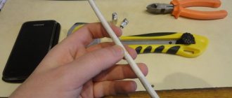
- For those who are used to doing everything themselves: prepare a grounding loop: metal fittings with a diameter of 20 mm (steel, stainless steel, copper are suitable). Cable wire (PV-16.0 sq. mm), as an antenna connector with a recessed circuit.
- Drive the ground electrode to a depth of two meters, leaving the end of the metal rod 20 cm above the soil. You must connect the wire to it using a clamp or welding. Connect the other end of the current collector to the antenna.
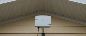
Saratov Electromechanical Plant has recently expanded its range of compact outdoor antennas. Let me remind you that this type of antenna was discussed earlier in one of the previous reviews.
And let's start with the new active antenna "Corsair 5v".
The antenna is supplied in a white rectangular cardboard box:
with information sticker:
By taking a photo in the lower right corner, we will receive a short link to the site with a description and information about the manufacturer:
Family of aluminum antennas “Corsair” More details: https://short.remo-zavod.ru/xv8y Russia, Saratov, SEMZ “REMO” [email protected]
The sticker also lists the main functions in the form of icons:
the Anti-GSM filter
at the amplifier input , designed to suppress radiation from cellular stations.
Here below we see a conventional range bar for which the antenna is intended: of course, it can receive further away, but in general, approximately within this range of distances from the transmitter.
In the upper right corner there is a note - “ Made from Russian aluminum ”:
We open the box and see inside the antenna, passport and warranty card:
To prevent the antenna from dangling and accidentally being damaged during transportation, it is all covered with bundles of air bags:
The antenna is supplied assembled:
and is a classic 5-element “wave channel”.
The measured dimensions of the antenna are 385 x 332 mm. The dimensions of the loop vibrator are 254 x 66 mm.
Measured weight: about 350 g.
Please note that the cable and connectors are not included in the package:
Attention: to connect the antenna to the TV, a coaxial cable and an F-connector are required, which are purchased separately.
On the leg of the antenna box there is an information sticker with the inscription - “ Active outdoor antenna of the “Range” series.” Manufactured by REMO Russia LLC :
Let me also remind you that at the bottom of the antenna box there are two drainage holes to reduce excess humidity during temperature changes: Opening the box we see a plate amplifier, screwed directly to the loop vibrator and soldered directly to the F-connector (without intermediate cables):
The single-stage amplifier is made on the already mentioned low-noise microwave transistor (approximate circuit):
The measured current consumption is about 9 mA.
Moreover, if necessary, the design of the antenna box allows it to be replaced, for example, with an amplifier from a “Polish” array or a passive one.
However, we must remember that according to the document:
3.4.6 RF Input Connector
Maximum load current 30 mA
Therefore, before replacing the original amplifier of active antennas with an amplifier from a “Polish” array, it is advisable to first measure its current consumption precisely at +5V. If the current consumption exceeds 30 mA, then in accordance with the requirements, the overload protection in the set-top box may trip and such an amplifier will not work.
There are also situations when the amplifier consumption from the “Polish” grid is on the verge of tripping the protection, so messages about overloading the antenna input power may sometimes appear on the screen. In any case, it is better to choose a more economical amplifier or choose among the 5V options (these have also appeared).
And of course, using a 12V amplifier when powered from +5V, the gain will be lower.
Reading the passport, it is noticeable that each time the description becomes more and more detailed, in particular in the section:
6. Assembly and installation procedure
6.3. When selecting the installation location and orientation of the antenna, pay attention to the examples shown in Fig.
And typical errors are shown in the form of schematic drawings. As you can see, some of them relate to incorrect orientation (not to the tower), and the other to insufficient antenna height:
Lack of height is most typical for the private sector, villages, and summer cottages, especially if they are located, for example, immediately behind a hill.
And here are the corresponding options for the correct direction and placement of the antenna:
I would like these pictures to be even larger and clearer, because unfortunately many people do not read the instructions at all; they will at least look at the pictures and see typical mistakes when installing antennas.
After all, like all manufacturers, the description of the antenna begins with the conditions of use:
1. General information
1.3. The range and quality of reception depend on the installation location of the receiving antenna, the height of its suspension, the power of the television transmitter, the height of the suspension and gain of the transmitting antenna, the terrain, the time of year, the level of interference and a number of other factors.
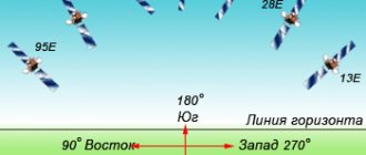
In order to know where to direct, you can use the updated service and now you can simply point the mouse at your house - it will show the exact direction (azimuth) and distance to the two nearest towers, for example:
The black end of the arrow shows exactly where the towers are located:
Knowing the right direction is also important because the digital transmitter is not always located on the same tower as the analog channels.
For example, in the Republic of Bashkortostan, absolutely all 216 towers will be new, but they may not necessarily be located somewhere next to the old tower, but in general - in any direction.
Therefore, it is better to focus not only on your neighbors’ old antennas, but also check for yourself where the digital transmitter is located, using the service.
Of course, if you have a need to catch a signal not from the nearest ones, but from some distant tower (for example, to catch 2 multiplexes), then you can measure the distance as usual using Yandex.Maps - using the ruler button (in the right bottom corner of the cards): place a point on your house and another point on the tower. We get the distance.
And it will allow you to quickly assess not only the distance, but also the relief on the route (if you are overloaded, there is one in English). Select 2 points on the map, and then click the button - Draw elevation profile.
An example of the result to a distant transmitter:
Well, it will help to see the signal path taking into account the curvature of the Earth : set two points, indicate the height of your future receiving antenna and the operating transmitting antenna, and click the 'Build path profile' button at the bottom:
The height of the transmitting antenna can be clarified, for example, at your Consulting Support Center or on the website in the Digital TV section.
Of course, curvature must be taken into account primarily for long-range reception - more than 60 km, and the antennas under consideration are designed mainly for the near and middle zones.
And you need to remember:
8. Certificate of acceptance and warranty
8.5. The manufacturer cannot guarantee high-quality reception of TV programs in areas of insufficient TV signal coverage and incorrect installation and/or configuration of the antenna. Lack of reception in such situations is not grounds for recognizing the antenna as faulty.
Reception parameters : loggia of the 7th floor of a residential building, surrounded by urban buildings and high-rise buildings. Near transmitter: 2 kW (area about 45 km), channel 27 is at a distance of about 15 km. The Quality scale showed about 78%:
And the long-distance transmitter: 5 kW (area about 60 km), channel 59 is approximately 78 km away. Quality scale - about 49%:
We used the same TVjet RE820HDT2 (HW Rev. 4.0) set-top box described in one of the reviews, and a 6 m long coaxial cable.
Because The antenna is active, but without an external power supply (like the Corsair DX model). Before setting it up, you must turn on the +5V antenna power in the set-top box menu, which is indicated in the model name - 5v .
If you do not turn on the power in the set-top box for an active antenna that does not have its own power supply, then the amplifier, and therefore the antenna as a whole, will not work.
It is best to adjust antennas to the maximum Quality scale in the evening, when the most difficult electromagnetic environment develops.
Let me remind you that after each slight rotation of the antenna, you need to wait 2-3 seconds for the response of the Quality scale.
Now let’s look at the “Parus 5v” model, which is functionally similar in many ways, but also has its own differences.
The antenna is supplied in an oblong cardboard box:
The colorful sticker also shows the functional purpose and basic information:
The QR code showed the following data:
Family of aluminum antennas “Parus” More details: https://short.remo-zavod.ru/bufd Russia, Saratov, SEMZ “REMO” [email protected]
The conventional range line here has been extended to a greater distance than the previous one: And there is also a note - “ Made from Russian aluminum ”:
Inside the box we see an antenna, a pair of reflectors, a bag of hardware for attaching them, a passport and a warranty card:
The antenna is also lined with AIRplus air bags to prevent the internals from moving or being damaged during transport.
Just screw on the reflectors and the antenna is assembled:
Measured dimensions - 475 x 332 x 263 mm. The measured mass is about 550 g. The mass has increased by 200 g due to a more expanded reflector and a traverse lengthened by 90 mm.
We mount the antenna on the wall bracket and connect the cable.
6. Assembly and installation procedure
6.5. After connection, waterproof the connector using PVC tape and neutral sealant.
Send to the nearest transmitter:
The Quality scale showed 100%. Expand to the far one:
Quality scale is about 75%.
As you can see, the expanded (more frequent) reflector gave an increase of about 20-25% on the Quality scale. This explains the greater range of the “Sail” in comparison with the “Corsair”.
And let me remind you once again about such a phenomenon as, which applies to all antennas, from the simplest indoor ones to complex outdoor ones.
Even if you are standing in an open field, at least two signals arrive at the antenna - direct and reflected from the earth's surface.
And signals even with the same amplitude, but with different phases, can result in different total intensity. Thus, the intensity of the sum of two signals can vary from 0 to twice the sum of the amplitudes.
If such a situation arises, then simply move the antenna slightly within a meter: closer/further from the transmitter or changing its height - lower/higher (higher is better, of course). Moreover, check the Quality scale on both multiplexes, because... This is also affected by the frequency of the incoming signal.
When making the final installation of any active antennas, you should also not forget about the potential threat of amplifier failure after a thunderstorm due to lack of grounding:
5. Indication of safety measures
5.1. To use the antenna safely, it is necessary to provide it with a protective ground. The ground may be connected to the threaded portion of the U-bracket of the mounting assembly.
And in general, any antenna must be periodically monitored:
7. Maintenance
7.1. Preventive inspection of the antenna must be carried out regularly, but at least once every six months, while paying special attention to the correct orientation of the antenna, reliability of fastening, tightness of all elements, integrity of the cable, and absence of mechanical damage to the antenna.
For example, if the antenna was not securely fastened enough, then in a strong wind it can be turned to the side, the Quality scale will fall, so you need to point it again at the tower to the maximum of the Quality scale and secure it.
Moreover, strong winds or thunderstorms can happen at any time, for example, at night, when everyone is sleeping, or you were not at the dacha, and during this time anything could happen there. Therefore, if it stops showing, then the check must be started with the antenna, cable, etc.
" Corsair 5v " Positive: more compact, because the attachment point to the mast is located in front of the reflector, a lightweight simple aluminum active antenna with the ability to be powered from a +5V set-top box, an Anti-GSM filter. Negative: single reflector.
“ Sail 5v ” Positive: slightly greater gain due to the frequent reflector, power supply from the +5V set-top box, Anti-GSM filter. Negative: A little heavier and bulkier.
In general, we can recommend “Corsair 5v” for reception in the near zone, and “Parus 5v” for reception in the middle zone. And despite the slightly larger dimensions, personal preference remains for the “Sail 5v”, as it has an extended reflector, which is important for complex reception.
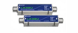
And in conclusion, let’s look at the USSh-5V antenna amplifier. It is designed to enhance the signal of passive antennas, for example, when it is necessary to compensate for attenuation on a long cable.
Supplied in a small colorful cardboard box:
On the reverse side are all contact details class=”aligncenter” width=”811″ height=”939″[/img] Inside there is the amplifier itself, a passport and a warranty card:
The input is a regular SAT-G antenna socket, and the output cable is a standard SAT-Sh plug.
The case is covered with heat-shrink tubing, however, you should not place the amplifier outdoors, because... it is not intended for this:
1. General information
1.5. The product can be used in the temperature range from +1°C to +40°C
And on the back of the passport there is a connection diagram:
Of course, you also need to enable +5V power supply in the set-top box menu. The “UHF P Range” model (P – passive) was used as a passive antenna. The set-top box and 6 m coaxial cable are the same as in the tests above.
Below is the signal level without and using an amplifier at 522 MHz:
and the same thing - at a frequency of 778 MHz:
As you can see, the signal level increased when using the amplifier. Of course, it is advisable to place the amplifier close to the antenna, optimally, for example, in the attic. Or directly in front of the set-top box, but you must remember that the cable between the passive antenna and the amplifier should not be too long.
The measured current consumption is about 22 mA.
Positive: compact, regular TV connectors are used. Negative: Not intended for external use.
When the antenna gain is slightly lacking, this amplifier will compensate for signal attenuation in a long cable.
The presented samples successfully combine excellent el. parameters and decent appearance. The antennas are made of aluminum, which increases their durability and reduces weight. Quite worthy representatives of the REMO for the city and suburbs.
4/5 — (12 votes)
You can ask questions about digital television on the DVBpro forum
Author: Alexander Vorobyov, 16 Sep 2015 | Permanent link to the page:
What not to do when grounding
As you know, the Russian people are cunning when it comes to invention. Often this trick turns against the owners themselves. The common myth that organizing residential grounding using jumpers in an outlet is a good example of this. Due to technical ignorance, and more often arrogance, residents resort to various tricks that have nothing to do with electrical safety. Regarding grounding your home TV network in case of a thunderstorm, know that no qualified electrician will advise you to do the following:
- attach the television antenna stand to the house ventilation duct or to the chimney;
- fix antenna cables near electrical cables or water pipes;
- use house engineering systems as grounding. Imagine what can happen when a powerful electric spark hits a gas pipeline!
Many have seen in films what happens when a hair dryer falls into a full bathtub. The same effect can be expected if lightning strikes a water supply or sewer network.