Home→Television→Connecting the antenna amplifier swa 777. All about antenna amplifiers
An antenna amplifier is a device that is installed on the antenna in order to strengthen the signal and, as a result, improve the quality of the picture on the TV screen. It will be especially relevant in areas far from television towers. As a rule, these are villages and villages located far from civilization.
Installing an antenna amplifier is necessary to improve signal quality.
There can be many reasons for poor signal reception. Even residents of large cities face this problem, although it would seem that they are in close proximity to the towers. The most common causes of interference:
- the signal source is too far from the receiving point;
- obstacles located in the signal path - trees, high-rise buildings, etc.;
- landscape gap between the signal reception point and the tower;
- weak signal.
The choice of antenna amplifier depends on many factors. However, the first thing you need to understand is what kind of antenna is installed. There are two types: passive and active. A signal amplifier is already built into the active antenna design by default. If you have problems with the signal, then most likely you have a passive antenna. Such an antenna should be installed only if the tower transmitting the signal is within sight and there are no obstacles between it and the antenna.
The next thing you need to find out is the distance to the nearest tower.
ADVICE. Depending on the distance to the tower, you should select a device with a suitable gain. As a rule, it is worth buying an antenna amplifier only if the distance from the tower to the house is more than 10 km. If the distance is shorter, then the problem is in an incorrectly selected antenna and the position amplifier will not correct it.
Gain is a characteristic that you need to be careful with. This is a case where more is not better. If there is a deficiency, the signal will not be strong enough, and if there is an excess, noise will appear, which will still interfere with high-quality broadcasting. For this reason, many amplifier models with different characteristics are produced for one type of antenna.
To select the correct coefficient, you must use a special table. There's nothing complicated about it.
Description
Installed in antennas: Meridian-07AF TURBO L025.07DT Meridian-12AF TURBO L025.12DT Meridian-60AF TURBO L025.60DT Ether-08A L035.08DKK Ether-08AF Turbo L035.08DT Ether-18AF Turbo L035.18DT
How to get to us
Address of our retail store: Moscow, Metro street 1905, Zvenigorodskoe highway, building 4, Shopping center “Electronics on Presnya”, Pavilion B-24 on the blue line
Working hours:
Mon-Fri: from 10.00 to 21:00 Sat-Sun from 10.00 to 20:00
All SWA definitions
| Acronym | Definition |
| S.W.A. | Shockwave audio |
| S.W.A. | Stephen Ward & Associates |
| S.W.A. | Southwest Airlines |
| S.W.A. | Special Weapons Agency |
| S.W.A. | Alliance for Sustainable Washington |
| S.W.A. | Standing wave apparatus |
| S.W.A. | Southern Wholesalers Association |
| S.W.A. | Sarawak Manufacturers Association |
| S.W.A. | Students Association |
| S.W.A. | Swedish Warmblood Association |
| S.W.A. | Scotch Whiskey Association |
| S.W.A. | Safe Workplace Association |
| S.W.A. | Secure access |
| S.W.A. | Armored with steel wire |
| S.W.A. | Wheel shaft assembly |
| S.W.A. | Windsurfing Students Association |
| S.W.A. | Saskatchewan Watershed Authority |
| S.W.A. | War Agency Special |
| S.W.A. | State workforce agency |
| S.W.A. | Water Source Rating |
| S.W.A. | The associations rushed to fight |
| S.W.A. | The ship will advise |
| S.W.A. | Small World Adoption Program, Inc. |
| S.W.A. | Sea of world aviation |
| S.W.A. | Single wire armor |
| S.W.A. | War Summary Estimates |
| S.W.A. | Purchasing a Standard Workstation |
| S.W.A. | Straight Antenna Wire |
| S.W.A. | Sliding windows algorithm |
| S.W.A. | Stacked broadband |
| S.W.A. | Slot machine stopwatch |
| S.W.A. | Simpson Weather Associates, Inc. |
| S.W.A. | Scleroderma Webmasters Association |
| S.W.A. | Ambulance South-West |
| S.W.A. | twisted wire armor |
| S.W.A. | SOAP messages with attachments |
| S.W.A. | Social work assistant |
| S.W.A. | Super White Army |
| S.W.A. | Super white arrow |
| S.W.A. | Solid waste administration |
| S.W.A. | Solid waste act |
| S.W.A. | Solid waste body |
| S.W.A. | Seriously wounded in action |
| S.W.A. | Shantou, China |
| S.W.A. | Swiss Windband Association |
| S.W.A. | Southwest Administrators Inc. |
| S.W.A. | Southwest Emissions, Inc. |
| S.W.A. | Southwest Asia |
| S.W.A. | Southwestern Archeology Inc |
Is the Polish grid suitable for receiving digital television?
The Polish mesh antenna at one time quickly spread throughout the country and gained popularity among many users. This equipment is easy to maintain and does not require additional modifications after installation. With the advent of DVB-T2 digital broadcasting in the country, users began to find various amplifiers for this type of antenna, allowing them to capture a digital signal and broadcast it to a TV.
The antenna array itself is broadband. In other words, such equipment is capable of receiving various signals of both meter and decimeter range lengths. This unique property allows the device to catch signals from digital TV channels in DVB-T2 format.
The Polish grid is not the most suitable option used for long-distance reception of digital TV channels. This is primarily due to the fact that the device requires modifications and modernization before it begins to function in the required range.
Wiring of the built-in amplifier SWA
A passive antenna can be amplified by installing an SWA card on it. The most delicate place in this process is the wiring of contacts. The video shows the entire process from choosing an amplifier to its correct installation. Just follow the recommendations and success is inevitable.
If your antenna with an amplifier does not stably receive a DVB-T2 digital television signal, then often the problem is not that the amplifier is weak, but that it is not needed there at all. Yes, yes, after the advent of digital terrestrial television, the situation with signal reception has changed a lot in some respects and in many cases, the amplifier in the antenna simply becomes unnecessary, moreover, it becomes the cause of an unstable and sometimes completely absent signal.
I have already written about the cause of this phenomenon and methods of combating it here, so I will not repeat myself and will not explain why the alteration is needed, which I want to talk about in this note. Namely, how to convert the amplifier for the “Polish” antenna into a matching board.
What will you need for this? Actually the amplifier itself, maybe even a faulty one, a 3 centimeter piece of wire and a soldering iron. Task: Make a matching board from the amplifier board, which is not always available in stores.
Let's start remodeling
Amplifiers from array-type antennas have a balun transformer, and we will need it to match the antenna with the signal consumer. In the photo below, the transformer is circled in yellow. (A similar modification can also be made in amplifiers for other types of antennas)
Matching transformer on the antenna amplifier board
There is no need to solder it, everything is much simpler. On the amplifier board, on the side of the radio elements, you need to remove the excess. Namely, unsolder the capacitor at the output of the transformer (marked with a red dot) and unsolder the strapping elements in the terminal circuit to which the central core of the cable is connected (marked in orange)
Attention! In amplifiers with other numbers, the number of elements and their location may differ, but the meaning remains the same, disconnect the transformer and terminal from the amplifier circuit.
Antenna amplifier with items marked for removal
This is how I did it! (Photo below) Of course, I washed all the soldering points with alcohol..... well, how did I wash it? — Rubbed with a thin layer, you know))) Although this is not necessary.
Amplifier with elements already removed
Final stage - Using a short wire, you need to connect the free output of the transformer to the terminal for the central core of the cable. That's it, the approval board is ready! You can install and try. And yes! Don't forget to use a regular TV plug instead of the power supply. The one with the separator from the power supply will not work.
Amplifier converted into a matching board
That's all! Found it useful? Share with friends, social media buttons below, this will help the development of the site. Thank you!
Types of amplifiers
We will not go into the intricacies of the design of the antenna amplifier - for the average person this information will be useless. Let's talk about two types of amplifiers and their purpose.
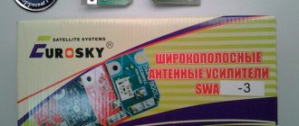
Amplifier SWA
SWA antenna amplifiers are used in ASP-4 and ASP-8 array antennas, which are often called “Polish” antennas. These antennas themselves have a very low gain, and they cannot do without an amplifier.
The two most important characteristics when choosing an SWA amplifier will be gain and noise figure. When purchasing, pay attention to them. We have already talked about the first above. With the second it’s still simpler - the less, the better.
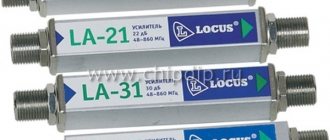
Amplifier LSA
This type of amplifier has a very narrow field of application. They are produced for repairing failed Locus antennas. Certain LSA models can enhance their corresponding Locus antenna models.
Reasons for a weak signal
The digital signal transmitted by the repeater may be too weak to be received for the following reasons:
- Large distance to the transmission tower. The same “inverse square law” applies to radio waves in the UHF range on which digital television broadcasts, as for any other type of electromagnetic radiation.
- Absorption of waves by the atmosphere. The air itself is practically radio transparent, but dust, fog, and moisture can scatter and reflect the signal.
- Obstacles in the path of radio waves. UHF broadcasting is received in the line of sight zone, the waves practically do not bend around obstacles. Therefore, if there is some object opaque to radio waves between the repeater and the receiving antenna (buildings, hills, a forest of tall trees), at best the signal will be weakened. This is more appropriate in cases where indoor antennas are used: any walls, even thin ones, absorb electromagnetic waves.
- Only reflected signals are received. If there is an object that screens radio waves on the direct line between the antenna and the repeater, you will only have to receive the television signal that will be reflected from other objects (for example, neighboring buildings). Such radiation is many times weaker than that initially broadcast from a television tower.
- Poor quality receiving equipment: antenna with low sensitivity, cable with high resistance, etc.
In a word, there can be a lot of reasons. In most cases, influencing them is difficult or even impossible. Therefore, in order to watch TV without freezing and scattering of the picture, you need to choose the right way to improve reception.
Power supply - adapter for antenna amplifier
If you open any power supply with an adapter, you will see a power transformer, four diodes, an electrolytic capacitor, a simple capacitor, a choke and a voltage stabilizer microcircuit.
All parts of the decoupling circuit, except the power transformer, are installed on the printed circuit board.
Electrical circuit diagram of the power supply for the antenna amplifier with adapter
The power supply shown above in the photo - an adapter for powering the antenna amplifier - is assembled according to a classic electrical circuit diagram. AC mains voltage 220 V is supplied to power transformer T1, which lowers it to 12-15 V. The diode bridge VD1-VD4 rectifies the voltage, the electrolytic capacitor C1 smoothes out the ripples, after which a constant voltage of about 16 V is supplied to the integrated voltage stabilizer DA1.
To eliminate video signal losses and loss of DC voltage, an LC filter is provided at the input of the television receiver, made on elements L1 and C3. Choke L1 does not pass a high-frequency television signal to the power supply circuit, but without losses it allows direct current to flow to the central core of the television cable coming from the television antenna amplifier. Capacitor C3 prevents DC current from flowing from the power supply to the TV input, but passes the TV signal without loss.
When making your own power supply with an adapter, parts can be used of any type. Typically, the current consumption of antenna amplifiers does not exceed 150 mA, which is less than 2 watts, so the transformer for the power supply is suitable for any power with an output voltage of 15-18 V. The choke can be made by winding it on a dielectric base, for example, a strip of fiberglass 5 mm wide, 25-18 V. 30 turns of enameled copper wire with a diameter of 0.1-0.5 mm.
Disadvantages of the presented design of the power supply with adapter
The disadvantages of a power supply adapter of this design include the presence of an unshielded section of the central core of the television cable at the place where it is sealed into the printed circuit board, which, in the presence of interference, for example from a working vacuum cleaner, can lead to interference with the video signal. The penetration of interference can be eliminated by installing an additional shield on the printed circuit board at the place where the wires are soldered.
Answers to questions about SWA and LSA amplifiers
How to properly connect a “Polish” antenna
Please tell me how to set up the TV and how to properly connect the Polish antenna (you need an amplifier). That’s why upon purchase it says that T2 is on the TV. But when setting up there is not a single channel. 12/14/2018, Ukraine, Dubensky district, village. Tarakanovo.
For the antenna to work, it is necessary to select the correct model of the SWA amplifier, attach it to the antenna and connect it to the network power supply through a separator. In addition, the antenna structure must be located at the point of best reception and directed towards the regional transmitting television tower.
Signal amplification methods
TV antenna signal amplification is achieved in 5 ways:
- Use a higher quality TV antenna than the one you have. Depending on the design, a few decibels of gain can be gained here. Check if your antenna is selected correctly.
- Precise orientation. Almost all devices operating in the UHF range have a clearly oriented diagram and most efficiently receive a signal from one direction. Even a rotation of 5–10 degrees can give a serious increase in signal strength.
- Replace cable. If the distance between the antenna and the television receiver is too large, the lion's share of the received signal power is lost due to the resistance of the conductor. This can be avoided by using a feeder with reduced resistance (for example, with a central core made of pure copper rather than copper-plated steel).
- Move the TV closer to the antenna. The cable becomes shorter: in some cases, even 2–3 meters can be decisive. Reducing the feeder length allows you to avoid unnecessary signal power losses.
- Use an antenna amplifier.
We will dwell on the last option in detail, since it often turns out to be decisive.
How to choose the right one
When choosing an amplifier, the TV owner needs to consider the following parameters:
- Required gain range. The device can separately amplify UHF and HF (this is useful if there are local stations transmitting analogue television signals in this range), can be broadband, that is, working with several ranges (however, losses in reception quality are inevitable: universal amplifiers are always worse than highly specialized ones) , or can be multi-band with several amplification blocks for each frequency range.
- Device type. The amplifier can be built-in (that is, a structural part of the active antenna) or external, connected to the cable.
- Type of food. Voltage can be supplied to the amplifier either via a coaxial feeder cable or directly from an external power supply. “Cable” devices are more compact, but amplifiers with separate power supply are more powerful.
Antenna amplifier characteristics
- Operating range: 50 MHz – 4000 MHz.
- Gain: 22.8 dB - 144 MHz, 20.5 dB - 432 MHz, 12.1 dB - 1296 MHz.
- Noise figure: 0.6 dB – 144 MHz, 0.65 dB – 432 MHz, 0.8 dB – 1296 MHz.
- Current consumption is about 25 mA.
More detailed specifications can be found in the SPF5043Z datasheet.
The low noise amplifier has proven itself to be excellent. The low current consumption is fully justified.
The microcircuit also perfectly withstands high-frequency overloads without loss of characteristics.
Making an antenna amplifier
Scheme
The circuit uses an RFMD SPF5043Z microcircuit, which can be purchased at -
AliExpress
.
In fact, the entire circuit is an amplifier microcircuit and a filter for its power supply.
Amplifier board
The board can be made from foil PCB, even without etching, as I did.
We take two-sided foil-coated PCB and cut out a rectangle measuring approximately 15x20 mm.
Then, using a permanent marker, draw the layout along the ruler.
And then you want to etch, or you want to cut out the tracks mechanically.
Next, we tin everything with a soldering iron and solder SMD elements of size 0603. We close the bottom side of the foil board to a common wire, thereby shielding the substrate.
Connecting the power supply
Although connecting the power supply does not require any skill, take the time to study the connection manual that comes with the kit. First of all, pay attention to safety measures.
Outdoor television antennas with an amplifier are always a bait for lightning, so do not carry out work during a thunderstorm, especially if your receiver does not have lightning protection.
There are three ways to supply power to the active antenna amplifier.
| If you have a digital tuner | Power is supplied directly from the set-top box via a coaxial cable. In the menu of the set-top box, find the item “Ant. on." Even if the amplifier is 12V, often 5V from the tuner will be enough. |
| In the absence of a digital set-top box | In this case, you need a USB powered antenna. If this possibility is not provided in the design of the wave catcher, then a special adapter with an injector will be needed. It connects to the USB port of the TV. |
| Classic way | The connection is made through a power supply with a voltage corresponding to the amplifier. Connect the coaxial cable to the plug, having previously stripped it - thread the cable under the fastenings and tighten the fastening screws. The coax must touch the tinned area with the braid. |
If connecting an antenna with an amplifier to the TV did not give the expected results in the form of an improved image, you need to try to change its direction or question the wave matching of the amplifier.
Antenna amplifier installation
Externally, the amplifier is a small electronic circuit. It is attached directly to the antenna itself using bolts and nuts. The amplifier will show greater efficiency if it is installed near the antenna on the mast, between the matching device and the feeder. The signal passing from the antenna through the feeder significantly reduces its level. After installation, you need to check whether the signal has improved. Without equipment, this can be done by simply turning on the TV.
If the antenna is already installed, it will not be difficult to connect the amplifier and, using a special adapter, power the power supply. However, if the antenna is not connected, then you will have to worry about running the cable to the TV. If you are not confident in yourself, then the best solution would be to call a telemaster who will quickly and efficiently complete this task.
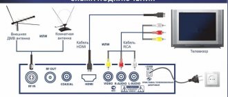
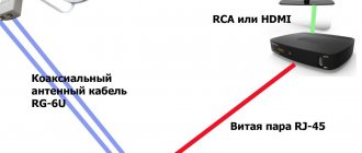
Connecting a TV cable to your TV
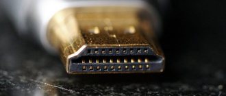
The first step is to select a television cable. This is a very important moment, since even an expensive TV will not provide you with a high-quality picture without the right cable.
The most common on the market are coaxial cables from various manufacturers with a characteristic impedance of 75 Ohms, brands RG 6U, SAT 50, SAT 703B and DG 113. Brands are listed in ascending order of quality. Marking is applied to the cable sheath along its entire length.
IMPORTANT. We will not describe all existing antenna cables, since this is not possible. However, please pay your attention to the following - the cable must have a characteristic impedance of 75 Ohms and the outer diameter of the sheath must be at least 6 mm. Adhering to these two criteria, you can choose the right cable.
After you have chosen a cable, it must be connected to a plug, since bare wires cannot be connected to the TV. Nowadays, F-plugs are the most widely used. Plugs are available in three different sizes to accommodate cables of different diameters. Be careful when purchasing - make sure the plug fits your cable. After purchase, all that remains is to install the plug. This can be done according to the diagram below.
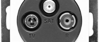
Antenna Grounding
However, that's not all. The antenna must be grounded before use. This is a very important and responsible procedure, and it should be approached with all responsibility.
IMPORTANT. Be careful! In the previous stages, the most you could ruin was the cable. When grounded, there is every chance of getting an electric shock - which can be fatal. Therefore, under no circumstances try to do grounding yourself! Call a specialist who will do everything quickly and efficiently.
If you live in an apartment building, as a rule, the antenna will be installed on a balcony or loggia. In such cases, there is no need for grounding, since it is already provided for when the house was built. Grounding will be relevant in a private house or on a summer cottage.
That's all. In this article we talked about the existing types of antenna amplifiers and how best to install them. We hope the article was informative and helped you in this difficult issue.
The antenna amplifier is not powered through a separate wire, but directly through the same coaxial cable through which the amplified signal enters. In this regard, connecting such an amplifier to an antenna and a TV has a number of features.