Another homemade product for those who are bored at home
I needed a couple of antennas for digital, in places with “not the best reception”... I went shopping (this was before self-isolation - if it’s relatively budget-friendly, then it’s complete G. The more expensive one looks decent, but how it works is questionable.
I decided to make something homemade. It was somehow awkward to “twist” an antenna from a piece of cable (although rumor has it it works) - I wanted something simple, but more decent and advanced
In fact, the one I made is not radically more complicated, but somehow more “solid” or something. And the results of its testing were very encouraging, so I decided to sketch out a short description of what and how, in case someone else finds it useful 
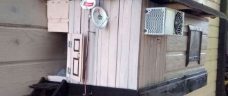
... even if my street cats have a “normal” antenna on their house, what can you do without an antenna?!
The wire is not all finished yet, now we’ll assemble something!
In the places described, I previously used home-made broadband log-periodic antennas, probably since the “beginning of perestroika.” They worked well in analog and not only on UHF, but “for some reason, digital was too tough for them.” I didn’t really delve into the essence of the reasons, I removed them and began to think about what to replace them with. Here is one of them, waiting for a place in the trash
A little history
In the early 60s of the last century, our compatriot Kharchenko K.P. developed a simple flat zigzag antenna with good characteristics.
Copyright certificate No. 138277 for an invention called “Band directional antenna” was issued to Konstantin Pavlovich Kharchenko in 1961 (according to his application dated June 16, 1960). In the same year, materials were published in the magazine “Radio” for repetition by radio amateurs.
The antenna is not critical to materials and dimensions during manufacturing, has a simple good match with the reduction cable, and it successfully combines multiple elements of a common-mode antenna array with a single feed point.
Theory and calculations
The described antenna, in theory, has a horizontal “figure-of-eight” radiation pattern and a relatively high gain, which can be further increased by using a reflector/reflector.
To obtain maximum gain on all channels, it is necessary to make an antenna approximately in the middle of the range between the multiplexes used.
Finding (for calculations) the frequencies of multiplexes used in your region is easy,
for example, a request like “dvb-t2 channel frequencies” + “Krasnodar”
I found something like this:
The middle, between “my” two multiplexes, is 700 MHz - we will calculate the antenna at this frequency.
As a basis for calculating the dimensions of the antenna, we take the drawing of its author
Calculate the wavelength: λ = 300 / f [m]
300/700 = 0.428m, approximately 43cm length of each side of the rhombus
λ/4
=43/4= 10.75
The total length of the material we need (11cm*8=88cm) is less than a meter. The distance between the reduction contacts, where we will solder the cable, is 10-12mm (the standard value for this antenna for frequencies below 900 MHz).
I will make a simple antenna, without a reflector, however, to further increase the gain of this antenna, it is quite possible to install it behind it
for example, from a metal mesh/grill, foil material or simply a metal plate. Its dimensions should be approximately 20 percent larger than the dimensions of the antenna and it should be located at a distance of ƛmax/7. For my case: wavelength (channel 39) 300/618, it turns out...49/7= that is, about 7cm
For those who are too lazy to do the calculations themselves
— you can use an online calculator, the results will differ only slightly from those I received. Here, for example, this one - here you immediately enter the frequencies of two multiplexes and get the dimensions of the antenna (without a reflector) Or another option, with a reflector - I really want to note that in the second option a slightly different calculation option is used, different from the author’s. An antenna with angles other than 90° is assumed and the reflector distance is calculated as λ/8
To make the antenna sheet, it is recommended to use aluminum or copper (copper is easily soldered) with a diameter of 3 mm and higher - the larger the diameter, the more broadband the antenna is. You can use tubes; the thickness of the walls is not important, since only the surface of the material is used (in fact, you can wrap any dielectric with foil to obtain the required material). However, in my opinion, the easiest way is to buy a meter of large-gauge copper wire at an electrical supply store.
With the beginning of the rapid development of television broadcasting networks in the early 90s, so-called Polish antennas became widespread. The cheapness and availability of such antennas contributed to their widespread use. However, this antenna has been widely criticized by professionals and qualified radio amateurs. Drying rack, rack, rear wall of the refrigerator. This antenna has received so many epithets. We now live in an era of widespread digital television. The question arises: is it possible to use such a frankly “under-antenna” for our show-off digital plasma. Or do you need to look for some kind of special, same fancy “digital” antenna? Let's answer this question by examining the digital model of our Polish girl...
First of all, let us immediately note the main shortcomings of this antenna, which led to such a low reputation of the Polish woman on these Internets of yours.
- An attempt to combine the incompatible and cram in the incompatible. This refers to long mustaches for receiving TV in the meter range. Since digital broadcasting is carried out exclusively in the UHF range, we can safely shorten this mustache to the size of the rest. As a result, we get an antenna array of four Butterfly antennas or fan vibrators (Bowtie). Such a vibrator has an electrical length close to the wavelength, a high input impedance, and at the same time, it is quite broadband.
- A set of directors on plastic guides has only decorative functions. Therefore, they can be safely thrown into the trash.
- The plate amplifier that comes with the antenna is prone to self-excitation. There is no input overvoltage protection; as a result, the amplifier often fails at the first thunderstorm. The tendency to self-excitation leads not only to interference on your TV, but also on the TVs of your closest neighbors. The lack of shielding and filters at the input and output of the amplifier leads to the fact that it picks up everything, including interference from car ignition systems.
- Plastic parts of the amplifier are quickly destroyed when exposed to solar ultraviolet radiation. The vibrators are attached to the collecting line using the same plastic. Over time, the contact point deteriorates as the properties of the plastic fasteners deteriorate and oxidizes. As a result, part of the “whiskers” spontaneously turns off.
A stack of four “butterflies” is quite popular among our overseas partners in the production of homemade antennas, almost more popular than the Hoverman antenna. True, they have to look for a thick wire and screw it on the knee to a wooden plank. But they are still happy and achieve good results. You and I, dear anonymous, can only sympathize with them, because we already have a ready-made inexpensive Pole. Is not it? All that remains is to make sure that the antenna has acceptable electrical parameters. To do this, we will use the Polish antenna model for the 4NEC2 program, which is available from our website.
What do we see? We see that the antenna's characteristics are rather mediocre, although in the upper part of the UHF range they can be called quite satisfactory. As the experience of overseas partners shows, using this scheme it is possible to make a quite decent antenna, only slightly larger in size compared to our Pole, but in this case, apparently, in the search for a compromise between the cheapness of the antenna and optimal characteristics, the scales tipped towards cheapness.
SWR>2 within half the UHF range. The gain throughout the entire decimeter range is 10-14 dBi, with the exception of the initial section where a dip is observed. If we take into account mismatch losses due to high SWR, then the antenna gain can be safely reduced by 2-3 dB at the beginning of the UHF range. High SWR in analog television leads to deterioration in picture quality and the appearance of noise and artifacts in the image. Digital television has its own characteristics, so a high SWR can simply lead to the inability to receive a certain multiplex, although a second one, on a different frequency, will work.
The radiation pattern is sectoral, more narrowed in the horizontal plane. Looks quite decent, i.e. The antenna has good directional properties. Among the shortcomings, it should be noted that the level of the rear and side lobes is quite large.
Having analyzed our Polish woman, we come to the conclusion that it is not we who should sympathize with our overseas partners, but they with us. After all, our Polish antenna does not have high characteristics. Of course it will work, because even a nail can be an antenna. But! No one can guarantee you the reception of all your multiplexes. There are several reasons for this. The antenna impedance varies over a very wide range with a high reactive component at certain frequencies.
This almost guarantees self-excitation of the unshielded SWA antenna amplifier that comes with the antenna. Old analog TVs had bandpass filters in the channel selectors. This somehow saved the situation. In any case, by adjusting the amplifier supply voltage, the interference could be driven outside the range and minimized. Modern digital tuners do not have such filters. There are only notch ones for the Wi-Fi frequency. As a result, powerful interference generated by the amplifier turns the input differential amplifier of the digital tuner into a nonlinear mode and reception of some or most often all multiplexes becomes impossible. In addition, in the absence of signal filtering, powerful extraneous interference may interfere with reception. Indeed, in comparison with the 90s, when the Polish antenna ruled the roost, the electromagnetic situation has deteriorated significantly. Digital data transmission networks and mobile communications have appeared, as have a large number of household appliances with switching power supplies that emit interference in a wide spectrum. All this together works against the use of a Polish antenna for receiving digital television. But you shouldn’t look for a special poncho “digital” antenna. If your Polish girl refuses to catch a number, before throwing it into a landfill and running to buy a new antenna, you should do the following:
- Shorten the top long mustache to the size of the rest;
- Throw away the plastic inserts with “directors”;
- Disassemble the points where the whiskers are attached to the collecting line and clean the contacts. Do the same at the amplifier connection point;
- Align the wires of the collecting line connecting the whiskers so that the antenna looks as “symmetrical” as possible. Align the mustache itself in the same way;
- Refuse the injector with the power supply and power the antenna amplifier directly from the TV or T2 set-top box by turning on the +5V power supply in the menu;
- Replace the old amplifier with a more modern one. Shielded, with an F-connector, with an inscription on the housing DVB-T2, powered by 5V. In this case, it is necessary to ensure that the collecting line does not touch the amplifier screen and, if necessary, insulate it;
In conclusion, we note that there are also homemade antennas optimized for digital television (including those with modifications to the Pole itself), the best of which we will present to your attention, in addition, the modernized Pole successfully works in CDMA data networks in the 800 band MHz.
Related links:
- Includes a full analysis of the more modern modification of the ASP8 antenna (poles), as well as other modifications of the “butterflies”.
- Results of using the Polish when receiving digital TV. (Remzon YouTube channel)
- .
- Kharchenko antenna optimized for digital television.
- DIY broadband wave channel for digital television;
- Features of digital television reception.
- VK()
- Facebook()
- Comments (22)
Comments
123
#21 Sergey A. 05/27/2020 10:09 And the gain on multiplexes 650 and 778 MHz is 12 and 14 dB, that is, higher than with a double bi-square?
Quote
#22 3G-Aerial admin 05/27/2020 11:58 You can safely reduce these two figures by 1 dB (at least the analysis in HFSS shows this) and we will come to the conclusion that the difference is not significant. Higher, but no more than 1-1.5. Our decibel scale is not linear, but logarithmic. Moreover, a difference of 1-2 dB is a relatively small value. She won't do anything for you. No one is stopping you from simply checking with your hands whether the Polish fish will catch or not. You should buy the feeder anyway. The passive symmetrizer for such a test can be replaced with a half-wave loop made from a piece of feeder, designed for the average frequency between multiplexes. There is a link to the calculation in the FAQ menu. If it doesn't work, you'll have to buy an amplifier. Doesn't work with an amplifier - needs alteration or selection of an amplifier. There is no need for unnecessary troubles with decibels.
Quote
123
Update list of comments
Add a comment
Comments from anonymous people (not registered site users) are pre-moderated. Moderation does not take place in real time and there may be a delay. We ask particularly impatient anonymous people not to publish the same post in a row. In this case, the post may be rejected by the moderator. Messages from disposable and non-existent emails are also deleted. The site has a forum and comments on social networks, where there are many more opportunities for communication.
©3G-Aerial
Antenna assembly
Let's remove the insulation from a piece of wire one meter long.
I got a wire with a diameter of 4.5mm
The tools you will need are a vice and a hammer. Measure approximately 11cm each and bend at an angle of 90°
The end result is to get such a “geometric” figure
We cut off the excess and solder the ends. It should look something like this...
Solder the cable as shown in the photo.
We lay the cable along one side of the square and secure it with clamps. This arrangement of the cable is necessary for its coordination (there are different opinions, not everyone agrees with this statement).
When using a reflector, the antenna sheet at the extreme points of the squares can also be secured using metal stands, for example, soldered onto the remains of the same copper wire - there are points with zero potential (highlighted in green). In other places, fastening is allowed only through a dielectric.
Wire antenna: the easiest assembly for a TV
You can receive a digital signal on a TV in a zone of up to 30 km using a simple single or double ring of copper wire taken with a 2.5 mm square piece of electrical wiring.
I show the technology of assembling it from two rings. If you are interested in a simplified version, then do not mount the second element.
The circumference of the ring must correspond to the wavelength of the TV signal from the transmitter. In my example, this is 48 cm. I bite off two pieces of wire: L1 and L2 with a centimeter margin for connecting the ends.
I bend future vibrators into rings and clean their ends. On a short section I make small rings to connect the second workpiece.
I insert one vibrator into another and squeeze the rings with pliers.
I show this process on a larger scale.
I prepare the end of the coaxial cable for connection by stripping the insulation.
I twist all the ends.
I solder the joints with a soldering iron.
The result is a simple antenna made of wire, consisting of two rings.
It should be oriented with the side of the long wire facing the transmitter. The rings can be bent into a hexagon shape. Then they will take a more stable position.
The photo below simply shows the principle: I did not give special accuracy to the dimensions of the geometric figure. Do better for yourself.
The antenna is assembled from wire. We turn it on and check the quality of the received signal on the TV.
Any soft toy will help to add decorative properties to the structure. This antenna should be located near the TV or receiver. It is undesirable to exceed the length of the coaxial cable by more than half a meter.
You need to spend less than 10 minutes to assemble such a structure, it does not present any difficulties, like the previous scheme, and its operation is due to the assembled loop.
Tests
And finally, a performance check and a rough
assessment of the quality of the resulting antenna.
In fact, everything is simple with the test - turn it on, it works! And to evaluate whether the game was “worth the candle,” let’s compare the parameters of the received signal from the manufactured antenna with the one I’m already using at the dacha, with a declared gain of 11dBi
The antenna is installed in the attic of a country house, at a distance of approximately 16 km from the tower.
Signal level: factory stationary antenna on the left / homemade on the right
At first glance, the difference is only 1% (95 versus 94) - but this is not a completely correct comparison, since my external antenna is connected through a splitter, which further weakens the signal.
Indoor antenna for digital TV
The use of indoor antennas for receiving digital TV is limited to areas with a high signal level, at a short distance from the broadcast site. This type of wave receivers is distinguished by a low intrinsic gain, and, unfortunately, the very frequent use of powerful amplifiers. This leads to the fact that, despite the attractive appearance and considerable cost, such a device may not be enough. Even if it is possible to catch a signal, the reception will be subject to local interference (walking around the apartment, turning on electrical appliances, cars passing outside the window), manifested by pauses in the air, freezing of the image or characteristic squares on the screen.
Assessing the performance of the antenna
Let's try to make a more correct comparison by connecting through the splitter input.
Well, in addition, for clarity, let’s add the number of participants List of antennas taking part in the comparison:
1. External antenna Funke BM 4551 external long-range,
declared gain, from some sources (bought at Yulmart), up to 16dB
2. There is an old UHF loop antenna, from TV Electronica 313d, I must say, despite its simplicity, it’s a very good antenna, that’s why it’s been preserved
3. I went to the store and bought for comparison in the review one of the cheapest, such as a symmetrical vibrator (100% the most purchased by pensioners, due to the low price).
I will carry out all “measurements” at one point, located as close as possible to the external antenna - its location was experimentally selected based on the maximum signal, so we can say that the conditions are approximately the same
So, we have already seen the signal level from the external antenna at 95% (at the time of current measurements it showed 94%), we take it as a standard. All comparisons are made by connecting antennas to the input on the splitter, to which an external antenna is usually connected.
Loop antenna, from Electronics 82% on 39 multiplex and 66% on 60
Budget with “horns” - 62%/38% (on the verge of losing the broadcast)
Double square - 92% on both multiplexes, about a couple of percent less than the external one
Out of curiosity, I decided to check the work of the reflector, which is easy to make from any metal mesh, plate or even foil... It REALLY works noticeably! The level rose to 96%!, which is even higher than the stationary one, with a declared gain of 11dB.
The most interesting thing is the object that I used as a reflector!
There was no foil in the house; the only thing available with a metal surface of the required size was... a laptop cover (I have a metal case). But the main thing is the result! It’s clear that I’m not going to “tie” the laptop to the antenna, and its amplification is enough for me without a reflector
What is an antenna for digital television
Fortunately, the antennas that are suitable for receiving digital TV packages (multiplexes) are ordinary wave receivers that previously received an analog signal. Although practice has shown exceptions. These differences most affected the operation of the so-called “Polish” antenna. Its versatility, relevant for an analog signal - reception in the meter and decimeter range - in the case of “digital” was manifested in additional distortions in the amplitude and phase of the captured signal. Designs like the “Polish” (aka “grid”) do not have a narrow radiation pattern, but catch radio waves in a wide range of directions, capturing other powerful signals that overlap T2 reception.
Many of our readers will find it strange to be reminded that satellite dishes are not suitable for receiving digital TV, but in fact, some users still try to receive over-the-air stations by confusing satellite and digital TV.
Of course, if you are installing a new wave receiver, it is better to buy a model adapted to “digital”. What is a simple antenna for digital television? The formulation of this concept boils down to the following - this is a highly directional receiver of decimeter waves, with reduced sensitivity to phase distortions. There are no other decisive differences between wave receivers for receiving analogue and digital TV in the UHF range.
You may be interested in: Stripping a television cable for the F-connector (connector)
Sometimes, under the brand name “digital antenna”, a device is offered, the design of which contains built-in filters to suppress signals from mobile communication towers that aggravate digital reception. This solution is often used in panel models with amplifiers. As for the latter, “digital” wave catchers are equipped with high-quality amplifying microcircuits that have a reduced level of phase noise.
Conclusion:
I can confidently recommend repeating it!
Simple, “cheap and tasty”... One of the simplest, indoor antenna mounts... with ordinary suction cups - if you’re lucky with the direction to the television center
The next antenna "recommended for repetition" is... log periodic
“Crazy hands” were with you. Good luck and good mood to everyone! ☕