Televisions, despite the advent of the Internet, are still “family members” and the main sources of information for many of us. The performance of the TV depends on many factors, including the serviceability of the antenna cable. Today we will talk about how to check this very serviceability and identify gaps.
Typically, such checks are carried out during repairs, remodeling, moving, or simply because of the need to replace an old or defective television cable.
Additional measures
A thorough visual inspection of the cable should be carried out.
In some cases, this method allows you to find the break point without using an ohmmeter. Typically, a bend may occur on the cable, which can be determined by the characteristic deformation of the core and braid, as well as by dents or cracks. Using these tips, you can easily determine the integrity of the antenna cable. Setting up television antennas at home is usually done using receiving and reproducing household equipment located in an apartment or house. The presence of a receiver and a TV in this case is sufficient to determine the signal level and correct it. We are, of course, talking about a primitive coordination of the elements of the chain, which includes an antenna, cable and television receiving equipment. For deeper settings, specialists use professional measuring instruments, which can greatly reduce the time of such work and simplify their implementation. The use of such devices makes it possible to determine the signal level in a matter of minutes and adjust the receiving antenna in accordance with the passport parameters of the receiving household appliance.
Comments
I changed the recorder and there is no image from the cameras
Yes, these are precisely the problems that often arise with systems. Our people are like that, they spoil the equipment themselves, especially when cameras are installed in public places, it is better to install everything out of reach of people.
Visually everything is fine with us. I'll check with a tester
Thanks to you and your recommendations, my husband quickly found our problem. Good luck and good clients.
We had a damaged cable. I had to call specialists. The technicians quickly fixed this problem by replacing the cable.
Thank you for the article. Helpful information. Indeed, a simple cable break often causes malfunctions in video surveillance systems.
Power supply for antenna amplifier
Power supply for antenna amplifier
The power supplies that accompany television antennas with amplifiers are manufactured at a minimum cost and with the same reliability. Since they usually operate around the clock, they often overheat and fail, even at rated AC voltage.
As mentioned above, power supplies for antennas are manufactured at a minimum cost, providing a current consumption of 20 mA at a voltage of 12 volts. However, they maintain good voltage regulation due to the use of a 12-volt stabilizer in the circuit.
Let's look at the antenna amplifier power supply circuit.
Standard antenna amplifier power supply circuit
From the diagram it can be seen that the antenna amplifier power supply consists of: a transformer with built-in fuse T1, a rectifier VD1-VD4, a low-frequency filter C5 and a high-frequency filter C6, a voltage stabilizer DA1, and a 12 V voltage indicator HL1. This circuit is an unregulated power supply for an antenna amplifier.
It is possible to adjust the signal level using an adjustable power supply for the antenna amplifier. The circuit is almost similar to the unregulated one, with one addition to the voltage stabilizer circuit at pin 2, a variable resistor is inserted into the gap, with which you can change the supply voltage of the amplifier.
With your own hands
The above circuit consumes excessive current from the network. If you modify it, you can end up with a more economical power supply with improved characteristics. Here is a diagram of an economical power supply for an antenna amplifier:
Resistors R1, R2 reduce the power supply's own consumption, the operating voltage of the problematic capacitor C5 has been increased, and additional filters L1C7 and L2L3C8 have been added.
There is nothing difficult about making a power supply for an antenna amplifier with your own hands. It should be remembered that a homemade antenna power supply must have low consumption and good stabilization, otherwise interference in the form of snow, slanting stripes and wide black stripes will appear on the screen.
Connection
To connect the cable to the power supply for the antenna amplifier, you need to connect the antenna cable to the plug. The first step is to prepare the cable. We retreat one and a half centimeters from the edge of the cable and make a thin circular cut,
Be careful not to damage the fine hairs of the screen under the outer layer of insulation. Remove the cut piece of insulator. Gently and evenly bend the hairs of the screen, it is better to remove the strip of foil. Stepping back 5 mm from the folded edge of the braid, make another circular cut of the inner insulator and remove it. Insert the cable under the fasteners and tighten the screws.
Please note that the metal braid must touch the bottom tinned area, otherwise power may not be supplied to the antenna. Do not allow the braid of the central core to touch, there will be a short circuit and the 12 V indicator light will not light up.
If the power supply for the antenna amplifier is correctly connected to the cable, as well as the cable to the antenna amplifier, then the TV will start showing immediately after setup.
Malfunctions
The main malfunctions of the antenna power supply include:
- Transformer malfunction;
- Stabilizer malfunction;
- Filter malfunction.
During voltage surges or overload in the secondary circuit, the fuse built into the primary circuit of the transformer may blow. This can be determined by measuring the resistance on the power supply plug. The absence of resistance may indicate a faulty fuse or a break in the primary winding of the transformer. To check the fuse, you need to cut the insulation on the transformer under which the fuse is located and check it for integrity. The fuse is usually located at the point where the network wires enter the insulation.
If the stabilizer malfunctions, the supply voltage of the antenna amplifier can either decrease or increase and lead to failure of the amplifier. This can be determined by measuring the voltage at the output of the power supply.
Failure of filter capacitors can result in significant image noise. The most common is the appearance in the image of 2 - 3 horizontal, wide black stripes, slowly moving across the screen.
As with any device, the operating life of the antenna amplifier power supply is limited. Should I turn off the antenna amplifier's power supply? If you are leaving for a long time, then yes it is necessary, but you should not turn it off every time you turn off the TV. As you know, most breakdowns of electrical appliances occur precisely at the moment of turning them on and off, and turning them off once again will not extend the service life of the antenna power supply, but they are quite cheap so that it is better to buy a new one later.
data-matched-content-rows-num=”4.8″ data-matched-content-columns-num=”1.4″ data-matched-content-ui-type=”image_stacked” data-ad-format=” autorelaxed">
TV plug
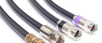
Previously, in order to connect a plug to a cable, it had to be soldered. Then they began to use antenna connectors, which are mounted by soldering bases. In the first models of this part, the central core of the antenna wire was screwed to the contact with a screw. And finally, they now use international standard type F plugs. Strictly speaking, this connector is simply a bushing that consists of two parts and is screwed onto the antenna wire.
In order for the TV to have a high-quality picture and the signal not to be lost, it is necessary to ensure that there is good contact at the connection point. If this seemingly simple task is not solved correctly, the TV will operate with noise in both image and sound.
To properly connect the antenna wire to the TV, it is not at all necessary to call a specialist. All manipulations can be done with your own hands using simple tools that everyone has.
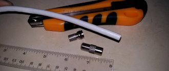
To solve this problem you will need:
- antenna cable (otherwise known as coaxial cable).
- F type plug.
- knife or stationery cutter.
This is interesting! How to hang a TV on the wall using a bracket
Antenna plug prices
What is a cable?
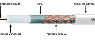
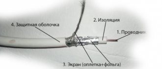
The antenna cable is a multilayer wire that, due to its shielding properties, can transmit a stable signal. It consists of a central core, copper wire, dense plastic insulation , aluminum foil (the second conductive element), shielding braiding that dampens interference and final external insulation, and protects against weather and mechanical influences.
The market now offers a wide variety of these products, both domestically produced and imported.
- When choosing a wire, you need to pay attention to the number 75 in the marking. It indicates the frequency of the resistance waves of this cable, which is what switching equipment and televisions are designed for. The marking must be present on the wire every meter along its entire length, next to the digital meterage mark.
- The next connector is an F-type plug. Connectors of this type are suitable for both analog and digital television signals. Since such plugs are produced in different diameter sizes, you need to pay attention to this. Make sure the plug matches the antenna wire for the TV. For those cases when the TV is mounted close to the wall, you can use the F plug of the corner design.
Testing multi-core cables for the purpose of marking them
When marking multi-core cables, you can use the methods described above, but there are ways to significantly simplify this process.
Method 1 : use of special transformers that have several secondary winding taps. The connection diagram for such a device is shown in the figure.
Using a transformer for marking
As can be seen from the figure, the primary winding of such a transformer is connected to the power supply network, one end of the secondary winding is connected to the protective shield of the cable, and the remaining terminals are connected to its conductors. To mark the wires, it is necessary to measure the voltage between the screen and each wire.
Method 2 : Use a block of resistors with different values connected to the cable wires on one side, as shown in the figure.
Resistors connected to cable terminals
To identify the cable, it is enough to measure the resistance between it and the screen. If you want to make such a device with your own hands, then you should select resistors in increments of at least 1 kOhm to reduce the influence of wire resistance. Also, do not forget that the value of the resistors has a certain error, so first measure them with an ohmmeter.
When checking a multi-core telephone cable, installers often use a dialing headset, for example TMG 1. Actually, these are two telephone handsets, one of which is connected to a 4.5 V battery. Such a simple device allows you not only to check the cable, but also to coordinate your actions during installation and testing.
Calling with a telephone handset
How to test wires with a multimeter
The most convenient, understandable and safe way to diagnose wires for continuity or short circuit is to check with a multimeter. There are a large number of multifunctional devices with different parameters and prices: from the simplest and most affordable to the more expensive, accurate and functional. But with almost any multimeter you can check the integrity of the conductors; you don’t have to have expensive equipment for this.
What should the multimeter readings be?
There are two methods of checking using such a device: in resistance measurement mode and in continuity mode.
The dialing mode is the most convenient testing method. Here you do not need to have any knowledge of the instrument readings. It is enough to connect the probes of the device to the ends of the cable and hear the sound. In order, the procedure is as follows:
Continuity testing is a test of a telephone cable for the integrity of the cores. The need for such a procedure may arise at any second. Your phone may stop working for a variety of reasons. For example, as a result of excavation work on the site, moving furniture in the house or after a thunderstorm. Also, the need for ringing may arise when carrying out electrical installation work - for example, when marking wires and cores, checking insulation. In any of these cases, it is important to know how to ring a telephone cable.
How to check the cable for a break?
You can ring a telephone cable in several ways - for example, using a special transformer, ohmmeter, megaohmmeter, etc. However, a telephone handset is best suited for these purposes. Such a device cannot be called either a tool or a device. At the same time, telephone operators most often use just such a handset. It is easy to use and mobile. This special handset can be bought in a store or made independently based on a handset from an old dial or push-button device. But how can you check a telephone cable for a break using such a handset?
Measuring the capacitance of a telephone cable should be carried out in the following order:
• Invite an assistant. • Identify the common core. This is any colored vein, for example green. This is where you need to start calling. All other veins will be called relative to this vein. • Connect one terminal of the main tube to this green conductor, and the other to any other desired conductor. • Connect one clamp of the auxiliary tube to the green wire (on the other side of the cable). Using the second clamp, switch through all the wires in turn. Find the core to which your assistant is connected. • When you connect the clamp of the auxiliary tube to the desired core, you will hear crackling and clicking sounds. This suggests that a closed circuit has arisen between the desired and green vein. • Through the tube, discuss with your assistant how you will mark the found vein. It is necessary to put tags with markings on both sides of the wire. Prepare them in advance. • Next, repeat everything described above, as many times as there are wires in the cable. • If a break is not detected, then crimp the entire cores using NShVI sleeve lugs and insert them into the terminal block.
What to do if there are no colored veins?
How to check a telephone cable for a break if there are no colored wires? Here you can start measurements from any core. You need to do the following:
• Connect one clamp of the main tube to the desired core. • Connect the second clamp to ground. If the cable is armored, then its armor can be used instead of ground.
All. Now you know how to ring a telephone cable. By making a call, you will be able to talk to your partner at a distance. You can, for example, specify the color of the cores. The cable can be located between different rooms or buildings. You don't have to walk from one place to another, which is certainly convenient.
Knowing how to check a telephone cable, you can quickly determine the reason for the lack of dial tone in the handset. This will allow you to take the right actions in a timely manner and establish communication.
is one of the leaders in the sale of cable products and has warehouses located in almost all regions of the Russian Federation. After consulting with the company’s specialists, you can purchase the brand of telephone cable you need at competitive prices.
Insulation check
To test insulation with a megohmmeter or multimeter, the principle of continuity is the same as when searching for an electrical connection between the cable cores.
The testing algorithm is as follows:
- set the maximum range on the device - 2000 kOhm;
- connect the probes to the wires and see what the device display shows. Considering that the wires have a certain capacitance until it is charged, the readings may vary. After a few seconds, the device display can display the following values:
- one, this indicates that the insulation between the wires is normal;
- zero – there is a short circuit between the cores;
- some average readings, this can be caused either by a “leak” in the insulation or by electromagnetic interference. To determine the cause, switch the device to the maximum range of 200 kOhm. If the insulation is faulty, the display will display stable readings; if they change, then we can confidently talk about electromagnetic interference.
Attention! Before checking the insulation of the electrical wiring, it must be de-energized. The second important point is that when taking measurements, do not touch the probes with your hands, this can introduce errors.
Video: Wire continuity check - integrity check.
Continuity tester for electrical circuits
There is a wide variety of wire and cable testers on the market. The difference between a tester and a multimeter is that its functionality is more modest.
The main purpose is to connect wires and check voltage. Therefore, many types of testers are not only a continuity tester, but also a voltage indicator.
It is quite natural that each such device has batteries for indication and signal, which need to be replaced as time goes by.
TV signal level according to GOST
The TV signal level is measured in decibels (dB), taken in relation to the effective voltage (1 µV). The designation looks like this: “dBµV”. In accordance with existing GOST, the value of this parameter should be in the range from 60 to 78 dBµV (these indicators are focused on a package that includes more than twenty programs). The optimal level of a television signal, at which the input signal-to-noise ratio has acceptable values (26 dB), is an indicator of the sensitivity of the television receiver. This parameter is specified in the device passport. Modern TV receivers are designed for a minimum input signal:
- 32 dBmV in the meter range;
- 37 dBmV in the UHF range.
Taking into account the fact that acceptable image quality is observed only at a signal level value that exceeds the receiver sensitivity rating by 20 dB, this value at the input of the receiving equipment should vary in the range of 52-57 dBmV.
In addition to this indicator, the signal characteristics are seriously influenced by such parameters as the ratio of signal to noise levels, as well as the level of intermodulation (nonlinear) distortion. Typically, such complex measurements are not carried out by specialists, but, nevertheless, the quality of the image largely depends on them.
According to existing standards (GOST [2.3]), the value of these parameters should not exceed:
- -72 dB/mW (70 µV) for meter range;
- -69 dB/mW (100 µV) for the UHF range.
The sensitivity of an individual video channel, taking into account the limitations associated with synchronization, directly depends on the minimum signal amplitude at the input of the television receiver, which ensures stable image synchronization. The meaning of these parameters is as follows:
- in the meter range it is acceptable within -75 dB/mW (40 µV);
- in decimeter - should not exceed -72 dB/mW (70 µV).
How to Measure Power and Improve TV Signal Reception
Article number: 00169218 / Last modified: 07/12/2018
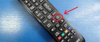
Note: The System Information screen can also be accessed by pressing HOME > Settings > Product Support > System Info > Press the green button.
3. The System Information screen appears with detailed information. The signal quality/power level indication appears at the bottom of the screen.
When is the signal strength good enough?
Ideally when the indicator readings reach the green zone
- You can only see the RED bar: The signal quality is poor. You'll likely encounter various picture and sound problems, and some channels and services will disappear from time to time or simply disappear. Try to improve the situation as described in the “How to find the cause of a weak signal” section later in this article.
- You will also see an ORANGE bar: The signal quality is acceptable, but it is recommended to improve it, otherwise noise may appear in the picture from time to time, the sound may be interrupted, or problems with the Electronic Program Guide (EPG) may occur.
- You see a GREEN bar: Excellent signal quality. You should not face any problems related to the channels or services.
Analog setup
1. On the remote control, press the HOME button > Go to Settings > Select Analogue setup.
2. Scroll to Manual Program Preset. 3. At the bottom of the screen you will see a signal strength indicator.
- RED bar: Signal quality is too poor. Try to improve the situation as described in the “How to find the cause of a weak signal” section later in this article.
- ORANGE bar: The signal quality is acceptable, but it is recommended to improve it, otherwise the image may have noise in the form of “snow”. Once at least half of the orange bar is visible, the signal can be considered valid.
- You also see a GREEN bar: Excellent signal quality within the limitations of analogue broadcasting.
Broadcasting problems
Depending on the problem you are experiencing, please try the steps below to optimize your (analog) over-the-air signal.
1-1. Poor signal/snow image noise/distorted sound
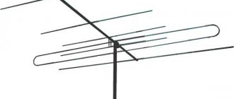
- Make sure your outdoor TV antenna is mounted high enough
- Make sure your TV antenna is in good condition and pointed towards the best nearby transmitter
- Your TV antenna may be broken or misdirected, and its connections may be corroded. If possible, try another TV (for example, your neighbors) that is connected to a different antenna.
- Make sure the antenna cable is securely connected to the receiver or TV; also check all other connections.
- Try changing the position of your antenna and see if this improves the image. A small change in antenna position can lead to significant improvements in reception.
No improvements? Have your antenna and its connectors checked by a professional antenna installer to ensure that your antenna and its connectors are working properly. You may need a higher quality antenna or antenna booster to improve signal strength.
1-2. Noise / dots / loss of color / hum / audio clicks / herringbone noise
- These symptoms are usually caused by electrical interference from appliances, switches, and computers in your home or your neighbors' home. The most common cause is a faulty boiler or central heating thermostat. They can lead to regular spikes in interference, for example 10 seconds every 20 minutes.
- Sometimes the source of interference can be high voltage electrical equipment outside your home.
- If you have a baby monitor or cordless phone, make sure it is not too close to the TV.
- If you have equipment such as a video player, DVD/BD player, or recorder, and the antenna cable is connected to that equipment, first disconnect the equipment from the TV, and then connect the antenna cable to the TV directly. This will help determine whether the equipment is causing interference. If you have multiple devices connected, connect them one at a time until you find the one that is causing the problem.
1-3. Smooth, evenly distributed horizontal stripes
- This is a sign of interference from a transmitter on the same channel and occurs when high air pressure (bringing good weather) allows signals to reach areas they should not normally reach. This can lead to signal weakening in low-lying areas. In this case there is no solution. Reception will only improve if the weather changes.
- If TV reception is poor during a rainstorm and remains poor after the rainstorm, water may have gotten into the antenna or the cable running from it.
Cable network problems
If problems occur, you may need to reconfigure the channels.
- Check that all cables are connected correctly and securely. Try using other cables of the same type, and replace the faulty cables.
- If all channels/services in your region are missing, the starting frequency/Network ID for your region may not be set correctly. By default, Frequency setting and Network ID setting are set to Auto ). In case of problems, please change Automatic to Manual and enter the correct data. You can obtain the necessary information from your cable operator. 1. To access the Tuning screen, press HOME on the remote control, and move to Settings > Select Digital setup or Analogue setup and press OK > Select Automatic setup (Auto tuning) and click OK > When the question “Do you want to start automatic tuning? (Do you want to start Auto Tuning?)", click Yes > Select Cable. 2. Now the Frequency and Network ID fields can be filled in manually. 3. To start searching for channels, click Start.
Problems with satellite reception
If you experience problems with satellite broadcast reception, please consider the following.
- Your satellite dish or LNB (this is the device mounted on a bracket attached to the satellite dish) is out of alignment. Please contact your satellite TV provider for proper dish settings.
- Rainfall may cause temporary loss of satellite communications. When the rain stops, satellite TV reception should be restored.
Does the problem persist? Retune your TV (Single Antenna Satellite Reception Guide)
Still haven't found a solution? Contact Sony for further assistance by clicking Support > Contact us on the Sony support website.
Source: https://www.sony.ru/electronics/support/articles/00094962
CHECKING COAXIAL CABLES
Coaxial cables that have become widespread are checked if the cable has been in use or is made up of separate sections. Before reuse, it is carefully inspected and subjected to simple electrical tests.
Particular attention is paid to the condition of the protective shell. If the latter does not have dents, cracks, swelling or other defects, then the inspection results are considered satisfactory. When inspecting a cable made up of individual sections, they find out how they are spliced.
The simplest electrical tests of coaxial cables include checking the integrity of the internal (colored Fig. 1) and external conductors, the absence of short circuits between them, and measuring the insulation resistance.
Operating principle
The device in question here allows you to measure resistance. It is very simple and completely safe to use.
Both ends of the cable will be needed to test continuity. It disconnects from both the receiving antenna and the TV. Very often this is impossible, because a collective cable is installed in the apartment, and in this case, for testing, you will have to open the antenna amplifier and measure the resistance of the core and braid.
When checking the integrity of an ordinary indoor cable using an ohmmeter, you must connect one end to the ring contact of the plug, and the other to the pin. Next you should pay attention to the indicators of the device:
- several tens of Ohms – stable signal (working cable);
- infinite resistance - open circuit;
- zero indicators – short circuit.
Finding the break point
After a break in the electrical wiring has been discovered, it is necessary to localize the place where it happened. For dialing in this case, you can use a tone generator, for example, the Cable Tracker MS6812R or TGP 42. Such devices allow you to determine the location of the break with centimeter accuracy, as well as determine the route of hidden wiring; in addition, the devices have other useful functions.
Model MS6812R
Devices of this type include an audio signal generator and a sensor attached to an earphone or speaker. When the sensor approaches the place where the UTP cable pairs or electrical wiring wires are broken, the tone of the sound signal changes. When a tone test is performed, the wiring must be de-energized before connecting the sound generator, otherwise the device will be damaged.
Note that with the help of this device you can test both power and low-current cables, for example, check the integrity of twisted pair cables, radio wiring or communication lines. Unfortunately, such devices will not allow you to determine the correct connection; special equipment is used for this purpose - cable testers.
Failure of LNB “heads”
Failures of LNB “heads” are also very common. Precipitation, short circuit, and overvoltage are the main causes of failure of satellite dish converters. To check the failure of a specific LNB, simply disconnect the drive (if you have several converters, of course) and connect the heads directly to the receiver one by one. In this simple way, you can quite accurately determine the faulty converter.
on Why the satellite dish does not work and there is no signal
Hello. This is the second time I have lost my Sirius signal. After replacing the head, the last time, the signal lasted for about 3 hours, then disappeared. I changed the connection to port 1, with a Sirius to Hotbird cable. Hotbird works, but Sirius doesn't. It turns out that disex + cable + port 1 hotbird signal passes, but port 1 + the same cable + working head there is NO signal. Astra and Hetbird are working. What could this be? Vladimir