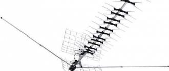
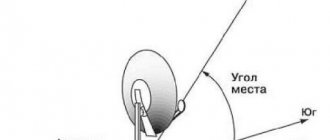
The three-element loop antenna has a narrow main lobe of the radiation pattern and high gain. For the UHF range, in which Russian 1, 2 and 3 multiplexes are broadcast in the DBV-T2 format, the antenna dimensions are very compact. Therefore, the “Triple Square” can successfully replace an indoor antenna.
The most optimal reflector rib length is 4% greater than the vibrator rib length. The dependence of the gain of the Triple Square loop antenna on the distance between the elements is shown in the figure. At B = 0.11L we have maximum gain.
The input impedance of an antenna, as well as its gain, is also determined by the distance between the antenna elements. For example, with a distance between the reflector and the vibrator B = 0.11L, we find that the input impedance of the antenna is 65 Ohms, and the gain compared to a half-wave dipole is 6.6 dB.
When calculating a Triple Square antenna, you can use the following formulas: B = 0.255L; P = 0.261L; D = 0.247L, where L is the wavelength. The optimal distance between elements is A (B) = 0.11. 0.15L. The dimensions of the elements for the UHF range (TV channels 21 - 80) of the Triple Square antenna are given in the table.
| Channels | D (mm) | V (mm) | P (mm) | A (mm) | B (mm) | W (mm) |
| 21 — 26 | 134 | 158 | 193 | 57 | 98 | 152 |
| 27 — 32 | 122 | 144 | 176 | 61 | 89 | 139 |
| 33 — 40 | 110 | 131 | 160 | 55 | 80 | 126 |
| 41 — 49 | 99 | 117 | 143 | 50 | 72 | 112 |
| 50 — 58 | 89 | 105 | 129 | 45 | 69 | 102 |
| 59 — 68 | 81 | 96 | 113 | 41 | 59 | 92 |
| 59 — 80 | 73 | 86 | 106 | 37 | 53 | 83 |
Frequency grid of television channels in Zhukovsky, Moscow region.
| Channel | Frequency limits, MHz | Average wavelength, m | Note |
| 24 | 494 — 502 | 0,602 | 3 multiplex |
| 30 | 542 — 550 | 0,549 | 1 multiplex |
| 34 | 574 — 582 | 0,519 | 2 multiplex |
Therefore, in this locality, the optimal antenna would be one designed for television channel 30 (Carrier frequency 546 MHz).
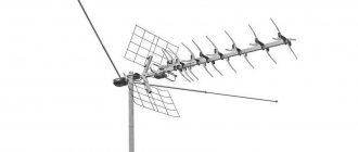
The Triple Square loop antenna can be improved by adding three more elements. The gain of the modified antenna increases significantly, which will give it an advantage when used both indoors and outdoors. The antenna design is shown in the figure,
Source: audiohobby.ru
EXTERNAL UHF ANTENNA WITH INCREASED EFFICIENCY, “triple square”
EXTERNAL UHF ANTENNA WITH INCREASED EFFICIENCY
The quality of television signal reception depends on many reasons. In urban conditions, interaction between the main wave of the TV signal and reflected waves is inevitable. With direct visibility between the receiving antenna and the transmitting antenna, the main wave and waves reflected from the ground, squares, streets, and roofs of buildings arrive at the receiving point.
For radio waves, a large modern city is, figuratively speaking, a pile of “mirrors” and “screens,” which are bridges, factory chimneys, and high-voltage lines. High-rise buildings, like a passive repeater, re-radiate waves from the transmitting antenna. The nature of radio wave propagation is very complex, even close to the transmitter. In the radio shadow of obstacles, a weakened useful signal is received, reflected signals, noise and interference become more noticeable. In wet walls of houses, in wet trees, the signal is weakened more strongly. The maximum attenuation of the signal received by an antenna located in the radio shadow of trees occurs in the summer. Adding and subtracting the main and reflected radio waves results in the strengthening of some television signals and the weakening of others.
Loop antennas in these conditions give good results due to the weakening of reception in the lateral and reverse directions; they are less susceptible to the influence of electrical interference and, in particular, interference from the ignition of internal combustion engines. For long-distance television reception, the most stable image is provided by loop antennas, one of which is described in this article.
Frequency range of received signals, MHz……530 – 780 Main received television channel….38 Range of received television channels…30 – 57 Polarization of received signals………horizontal
From a wide variety of loop antennas for the UHF
“triple square”
antenna is often made . What to do if the triple square gain is not enough, and other antenna designs are not suitable for the range of television channels of interest? At the same time, there is absolutely no place to get a sufficient number of aluminum tubes of the required diameter and specific fasteners; there is no way to assemble and install an antenna, the dimensions of which are measured in meters. Can I use an antenna amplifier that will amplify the main wave of the TV signal along with the reflected waves received by the antenna? The solution to this problem was to combine four triple squares into an antenna system - a phased array. The antenna gain is much greater than a single triple square, and the dimensions are quite acceptable. The dimensions of the design of one of the four triple squares are shown in the figure.
To make a triple square, you will need galvanized steel wire with a diameter of 3 mm. Galvanized wire is a wire that has a tin coating. Such wire is easier to coat with solder and does not rust in the open air. To make one triple square, 2 meters of wire are required. The piece of wire should not have sharp bends, dents, scratches, rust or other defects. Before making the antenna, the wire blank is thoroughly wiped using a solvent. The wire is bent according to the pattern showing the triple square construction. The wire joints at the top of the squares are soldered. Sections of the wire at the joints are coated with flux prepared from hydrochloric acid by etching with zinc. Using a soldering iron with a power of forty watts, or better yet sixty watts, areas are covered with low-melting solder, as much as the power of the soldering iron allows. Then the joints are pulled together with one or two turns of tinned copper wire with a diameter of 0.6-1 millimeter and soldered again. Finally, the joints are well soldered over the burner of a gas stove, using solder and rosin. The remaining rosin is removed from the resulting structure and washed off with a solvent. The junction must be well covered with tin, ensuring reliable contact and mechanical strength. Triple squares cannot be painted or varnished.
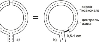
Before combining triple squares into a phased array, each must be tested and adjusted. Testing and adjustment is carried out indoors. A television coaxial cable with a characteristic impedance of 75 Ohms is connected to the triple square as shown in the figure. The image on the TV screen when setting up the antenna indoors can be black and white with a lot of noise.
The triple square setting is performed based on the least amount of noise on the TV screen. If one triple square does not produce a color image, it doesn’t matter; when combined into a phased array, the image quality will improve significantly. Having connected the triple square to the antenna input of the TV, you need to find the point of soldering the cable to the lower vertical part of the antenna structure, moving the connection point vertically. When moving the connection, the cable center core and cable shield must be connected at the same level. In some instances of the triple square, the best image on the TV screen can be obtained by soldering the cable almost at the closing horizontal section at the very bottom of the antenna, in other instances as shown in the figure, in the third instances in the middle. Each triple square has its own optimal cable connection point. After completing the setup and checking the triple squares, it is important not to mix up the cable connection points.
To obtain good quality antenna performance, you should make 6-8 triple squares, from which select four that give the best results.
The triple squares, which are phased array elements, are connected by a coaxial cable. The basis of the antenna design is a wooden frame. The length of the vertical cable sections connecting two triple squares is selected experimentally. It is impossible to accurately determine the length of cable sections in advance due to differences in the parameters of different types of cable and the unpredictable properties of manufactured triple squares.
Two triple squares are secured by wrapping a polyvinyl chloride tube on one vertical frame element, which is a wooden block. Alternately, identical sections of cable with a length of 220, 240, 260,280, 300 millimeters each are connected to the triple squares. The opposite ends of the cable sections are connected screen-to-screen and core-to-core and connected to the cable going to the antenna input of the TV. Based on the best image quality, the length of the vertical cable sections connecting the two triple squares is selected. The main contribution to the adjustment is the length of the cable sections compared to the distance between the triple squares. When setting up, you can shorten or increase the distance between the triple squares, but this will not give much effect, so the distances between the triple squares are not shown in the design figure. The image on the TV screen should be better than with a single triple square reception.
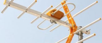
DIY Kharchenko antenna for digital TV
One of the most common options, which was proposed back in the 60s of the last century. Despite its considerable age, Kharchenko’s double square is successfully used not only for a television signal, but even to improve mobile communications and the Internet.
A simple zigzag design and the ability to be manufactured from available materials with good reception quality are some of the most important advantages of such a device. The main thing is the correct calculation.
What kind of antenna will you make with your own hands?
KharchenkoTurkina
The main indicator that must be taken into account is the wavelength at which the TV signal is transmitted. It is directly related to frequency. The easiest way to calculate this is to divide 300 by the frequency listed in the multiplex data. The length of the side that the square or rhombus should have will depend on this value. By the way, Kharchenko antennas are sometimes made in a different configuration, but they have not received much use for T2.
So, the side size should be 4 times smaller than the wavelength of the signal. With errors even within 2-5 mm, a significant decrease in the quality of the TV signal is possible. To improve reception, the antenna is placed on a homemade reflector, which is often used as a regular grill grate.
Devices of this type work more successfully when installing an additional amplifier, which is selected taking into account the signal characteristics in your area. In this case, it is better to organize power for the antenna using an adjustable power supply. You can see the simplest example of a Kharchenko antenna in the photo.
Why is this one of the best antennas
The scheme was first published in 1959 in the magazine “Radio”, where the enthusiast S.K. Sotnikov proposed a method for ultra-long-range television reception in the MW and UHF bands.
The author argued that using a three-frame design it is possible to achieve a gain of up to 17 dB. And although later calculations showed that the real coefficient is much lower, the antenna remains relatively simple to manufacture and an easy-to-use design, not inferior in characteristics to a wave channel, but at the same time much more technologically advanced to manufacture.
It is a structure consisting of three squares (director, vibrator and reflector) mounted on common guides. Metal frames (made of wire or thin tubes) of gradually increasing linear dimensions are placed on one or two common guides.
It is also possible to manufacture the Sotnikov antenna in a version where each of the elements is attached separately to a common base.
With the transition to digital TV, it has become one of the most popular long-range designs, which can be made in a short time at home. Suitable for use both indoors and outdoors.
- High gain for homemade - about 9 dB.
- Easy to make. It is easier to calculate and assemble than a classic log-periodic antenna for the UHF range.
- Extremely sensitive to changes in linear dimensions. Before manufacturing, you will have to find out the broadcast frequency of your repeater, carry out a thorough calculation of the antenna, and during installation maintain the dimensions to the nearest millimeter.
- Narrow band. You can effectively catch only 1–2 digital TV multiplexes from a distance. This is enough for most of Russia, but in Moscow or Crimea, where the third multiplex operates, you will need another antenna or you will have to put up with a drop in range.
- Difficult to enhance. Works great at distances up to 50 km from the TV tower. But if it goes further, then if you use an incorrectly designed antenna amplifier, there is a risk that it will go into self-excitation. Then there will be no talk about any quality of reception.
Types of UHF-T2 devices for high-quality terrestrial television reception
You most likely will not be able to watch TV on a digital DVB-T2 signal at your dacha using a standard indoor antenna. Here you will need a digital antenna. However, you should know that there are no “digital” antennas as such. And there are:
- terrestrial antennas;
- antenna amplifiers;
- coaxial cables.
So, if there is a signal matching board (balun) on the coaxial antenna cable, then this is a passive version of the antenna. And if there is also an amplifier with a power supply, then the antenna is active. The division of such antennas into active and passive types is the very first, main classification.
In addition, the following are suitable for receiving a digital signal in the country:
- decimeter antennas (UHF);
- broadband antennas (MV-UHF).
In this case, the recommended format is multi-director, which allows you to point the antenna directly at the repeater. (The most effective is the broad-directional type of antenna.)
Meter wave range
If desired, you can adapt an antenna for decimeter waves to receive a digital signal. However, if there is only a complex antenna available for both the meter range (MV) and the decimeter range (BMW) - the so-called indoor multiwave, then you can use it too. Here it will be quite simple to connect the SWA 9 modular unit to the antenna. It is a regular DVB-T2 antenna signal amplifier.
The meter range antenna is not designed to receive a digital signal.
UHF (UHF)
In general, a digital television signal broadcast in the DVB-T2 format is transmitted in the same long-wave range as UHF waves.
The difference in practice is that in the case of a digital signal it is impossible to increase the range of one’s own location in relation to the repeater due to deterioration in picture quality. The signal is either present or it is not.
Also a characteristic feature of “digital” is the high quality of the transmitted image (of course, if it is present). Any UHF antenna is suitable for receiving a DVB-T2 signal.
What is needed for production
You can make a TV antenna from various materials - from copper wire to aluminum tubes. However, the easiest way to assemble it is using the following tools and materials:
- steel or copper wire with a length of at least 2 m (if steel is used, it is better to take galvanized wire - it rusts less outdoors, which does not impair the performance of the antenna);
- coaxial cable for transmitting a signal to a set-top box or TV;
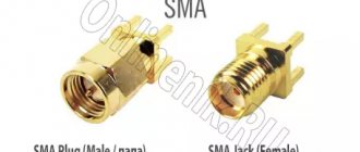
- RF plug ;
- a soldering iron for connecting wire elements and soldering the cable to the antenna (fastening with clamps, as for a biquad, is not suitable here);
- frame for fastening (can be made from anything, the main thing is that the material is either dielectric or mounted on insulating pads).
Half argument (angle) formulas
04.1)Sine of half angle
sine of half angle formula04.2)Cosine of half angle
half angle cosine formula04.3)Tangent of half angle
tangent of half angle formula04.4)Cotangent of half angle
half angle cotangent formula04.5)Tangent of half angle
tangent of half angle formula04.6)Cotangent of half angle
half angle cotangent formula05)Calculator
Since the “triple square” is a narrow-band antenna, it should be manufactured using a drawing and detailed linear dimensions of all elements.
To make it you need to know exactly the following:
- dimensions of the sides of the squares (in the diagram - R, V and D);
- distance between squares;
- the length of the matching half-wave loop (H in the diagram);
- thickness of the cable (W in the diagram).
Formulas for the sum of trigonometric functions
09.1)Sum of sines
sum of sines formula09.2)Sum of cosines
sum of cosines formula09.3)Sum of tangents
tangent sum formula09.4)Sum of cotangents
formula for the sum of cotangents09.5)Sum of sine and cosine
formula for sum of sine and cosine10)Manufacturing instructions
The antenna is made as follows:
- Three squares of wire are bent according to the calculated dimensions. In this case, the middle one is immediately made with a branch-loop: without it there will be no coordination.
- The ends of the wire of two squares (director and reflector) are soldered together. The vibrator still has a gap: the cable will be soldered here.
- A wire jumper is soldered on the side opposite the antenna connection point. Its task is to carefully maintain the distance between structural elements. In this case, you need to ensure that the central points of all three squares are on the same straight line: this will be the receiving direction for the antenna.
- The feeder is soldered into the loop gap. In this case, the central core should be soldered to one end of the wire, and the screen to the other.
- The cable is attached along the cable. This will help avoid discrepancies during approval. The cable can be left vertical or bent perpendicular to the plane of the vibrator.
- The wire is painted or varnished to protect against possible corrosion.
The antenna is ready. It can be mounted (usually on a rod made of non-conductive material) and configured to receive channels, orienting it along the compass towards the nearest repeater (you learned the direction from the CETV map before the calculation).
Here is a detailed video instruction for manufacturing without soldering:
There is also a second manufacturing method. Perhaps it will seem easier to someone. To do this, the wire is not cut into pieces, but bent so as to form a single antenna structure.
In this case, you will also have to solder the places where the elements are joined, but there will be fewer such nodes, and the structure itself will be stronger.
An improved diagram of its assembly is presented in this video:
There are a few tricks to keep in mind when making a "triple square":
- If galvanized wire is used, the soldering areas are first cleaned to bare metal.
- Since high-frequency currents (and they will be induced from the UHF, in which digital television broadcasts) propagate primarily in the outer layer of the conductor, the wire must be clean. Any traces of corrosion should be removed using fine sandpaper or a file.
- The material from which the antenna is assembled is important, but not fundamental. If you use thick copper or aluminum wire instead of steel wire, there will not be much difference in the quality of reception. Problems can only begin when making a “triple square” from aluminum, copper or steel tubes: then the design will need to be recalculated.
These are the structures assembled by radio amateurs:
Source: prodigtv.ru
Primary requirements
Receiving devices operating in the decimeter wave range have a single principle. The picture will definitely be clear if the television signal is strong enough. To make sure of this, you can ask your friends or neighbors in the country who use a digital antenna if their TV shows.
To reduce the level of interference behind the antenna, you can install a reflector yourself. It is used for devices that pick up analog signals and can affect the digital reception quality of square-type antennas. The reflector is installed behind the central square of the device.
No complex calculations required. To be completely sure, you can calculate the required square size. To do this, you need to find out the wavelength and divide it by 4. The resulting number will indicate the desired side of the outer square. The sides of the central squares should be 2 cm larger than the sides of the side ones.
Materials for the manufacture of antennas are selected taking into account current conductivity and the ability to change shape. Copper or aluminum tube and wire conduct current well, bend and are suitable for long-distance reception. Glass elements wrapped in foil can be used.
The receiving device must have several lanes and be directed towards the repeater, without encountering obstacles in the form of trees and houses along the way.
DIY antenna. Calculating the location of the tower is simple - by turning the antenna from side to side until a picture or message appears on the TV screen indicating sufficient signal strength.
Triple square antenna for dvb t2 calculation
Read more about the design in the corresponding article. We do not recommend a triple square antenna for receiving digital television. In any case, for receiving several multiplexes simultaneously. You can read more about why here.
Schematic representation of the antenna:
Dimensions are taken along the axes of the wire (from center to center), between elements (vr, vd) - from plane to plane in which each element is located. The planes are parallel to each other. The central points of the squares are located on the same axis. The cable can be bent from the side so that it remains perpendicular to the bottom side of the vibrator frame. Direction of reception towards the director. The polarization of the antenna in the diagram is horizontal. For a vertical one, you need to rotate the structure 90° around its axis, with the train to the side (no matter left or right). The frames are attached to each other using dielectrics. Electrical connection is allowed at the top points of the frames. You can bend a structure from one piece of wire as in the diagram on the right.
The calculator was updated on 01/04/2015; for correct calculations, do not forget to refresh your browser cache Ctrl+F5!
Data networks require a relatively wide antenna bandwidth. To achieve this, it is necessary to use thick wire to make the antenna. However, in other cases, for example, if the antenna is designed to receive one multiplex in digital television, the thickness of the wire can be reduced. This calculator has been modified to take this into account. You can choose one of 4 antenna options: 50 ohm antenna input impedance with thick and thin wires and 75 ohm antenna input impedance also with thick and thin wires.
The Triple Square antenna calculation has been added to our Android application Cantennator . Tap on the QR code if you came here from a mobile or tablet, or scan this code with your mobile if you are viewing this page on a desktop monitor to go to Google Play to download. Don't forget to rate the app and leave a review.
Source: 3g-aerial.biz
Formulas for adding and subtracting arguments
08.1)Addition of sine arguments
formula for adding sine arguments08.2)Addition of cosine arguments
formula for adding cosine arguments08.3)Addition of tangent arguments
formula for adding tangent arguments08.4)Addition of cotangent arguments
formula for adding cotangent arguments08.5)Subtracting sine arguments
formula for subtracting sine arguments08.6)Subtracting cosine arguments
formula for subtracting cosine arguments08.7)Subtracting tangent arguments
formula for subtracting tangent arguments08.8)Subtracting cotangent arguments
formula for subtracting cotangent arguments09)Earth on VHF or demystification of double/triple square antennas
In 1959, in No. 4 of the Radio magazine, a landmark article by long-distance television reception enthusiast Sergei Kuzmich Sotnikov was published on the use of “double and triple square” antennas for long-distance television reception on HF (and later on UHF).
The declared phenomenal characteristics of 10-12 dBi for a double square and 16-17 dBi for a triple square excited the minds of the Soviet amateur radio community and for many decades predetermined the enormous success of such antennas on HF and UHF: descriptions of these antennas wandered from book to book, from magazine to magazine . Thousands of Soviet citizens repeated them. Although these characteristics are very overestimated, they were still based on the publications of authoritative researchers: Sam Leslie (W5DQV, published in 1955), Dick Beard (G4ZU), Rothhammel (with reference to Leslie and Beard).
In 1962, Vladimir Pavlovich Sheiko-Vvedensky (UB5CI) published the book “Antennas of Amateur Radio Stations” in the DOSAAF publishing house, which also contains references to 13 dBi from a double square.
A large abundance of authoritative sources has determined that Sotnikov’s fundamentally incorrect conclusions are popular even in 2018.
Let's try to figure out where the truth borders on hoax here.
Rothhammel's book (translation by Krenkel in 1967) discusses HF antennas in the range of 20, 15 and 10 meters (14, 21 and 30 MHz).
With reference to radio amateurs Sam Leslie (Oklahoma, W5DQV, publication of the results of extensive experiments with squares in 1955), and Dick Beard (G4ZU, England), it is stated that double square antennas on these bands have directivity from 10 to 13 dBi (8 to 11 dBd)
Simulation in 4NEC2 with ground (Sommerfeld-Norton real ground mode) fully confirms these observations: with “moderate” ground conductivity you can get 12.4 dBi, and with “perfect conductor” 13.8 dBi at an antenna height of 1λ.
It should be noted that in the experiments of Leslie and Beard, dBd was measured not relative to the actually constructed dipole, but by measuring the field strength at a certain distance, with a known power in the TX antenna and comparing the measured strength with the calculated one using the Friis formula.
The fact is that an ordinary Hertz dipole, which has 2.13 dBi, with a suspension height of 1λ on HF forms a two-lobe pattern with a maximum of 8.2 dBi. Those. The dipole itself, due to the ground, has an advantage over itself of 6.1 dBd
Leslie and Beard's measurements are given relative to an imaginary dipole of 2.13 dBi, and not by switching the double square and dipole antennas alternately.
The 2-element wave channel (reflector + vibrator) also has a radiation pattern almost identical to the “double square”: 11.8 dBi with an antenna suspension height of 1λ with the ground conductivity “moderate”. The shape of the main and 3 side lobes is almost identical to the double square pattern.
Since there are no free-space antennas on HF, the methodology and data obtained are completely relevant and have practical application. These antennas cannot be measured in free space on HF.
Double argument (angle) formulas
02.1)Sine of double angle
double angle sine formula02.2)double angle sine formula02.3)Cosine of double angle
double angle sine formula02.4)double angle sine formula02.5)Tangent of double angle
double angle sine formula02.6)Cotangent of double angle
double angle sine formula03)Recommendations for use
The Kharchenko antenna has been actively used in households for more than one year, therefore, in order to ensure the longevity of its operation, it is recommended to periodically look after and care for it.
There are a number of recommendations
Here are some simple tips for long-term operation of the device:
- The connection between the cable and the antenna frame can be protected from external influences by wrapping it with regular electrical tape. However, this method is not permanent. It would be better to fill everything with glue.
- For the housing, some people use regular bottle caps or plastic jar caps. Recesses are made in the right places for normal cable exit. After which, everything is filled with a special sealing compound.
- When using an amplifier for a Kharchenko antenna for digital TV, the second square is not necessary.
- Also, for additional reinforcement, a double biquad is constructed. Everything is mounted in the same way as the regular version, but instead of the corners there are additional squares. As a rule, there are an even number of them. Their calculation is not necessary, because they must be similar in size to the main biquadrat.
That’s it, Kharchenko’s DIY television antenna is ready for using digital TV.
Formulas for the sum and difference of various trigonometric functions
13.1)Sum of sine and cosine
formula for sum of sine and cosine13.2)Difference between sine and cosine
formula for the difference between sine and cosine13.3)Sum of sine and cosine with coefficients
formula for the sum of sine and cosine with coefficients13.4)Difference between sine and cosine with coefficients
formula for the difference between sine and cosine with coefficients14)Formulas for the difference of trigonometric functions
10.1)Sine difference
formula for difference of sum of sines10.2)Difference of cosines
formula for difference of sum of cosines10.3)Tangent difference
tangent sum difference formula10.4)Cotangent difference
cotangent difference formula10.5)Difference between sine and cosine
formula for the difference between sine and cosine11)Assembly phase
After the structure is ready, you need to attach a television cable to it.
The Kharchenko antenna for digital TV will require approximately three meters. Moreover, from the antenna side it needs to be stripped by two centimeters, but from the plug side – by one. If there is excess length, unnecessary material can be cut off during work.
You can choose any plug you like. The main thing is that he comes to the TV.
The plug also needs to be cleaned. However, before this, the places where soldering is carried out must be wiped with alcohol and cleaned with a file.
Place part of the plug on the cable and solder it.
After all the joints are cleaned, they are filled with hot glue.
After the glue dries, the cable is connected to the frame. Thus, confirming the absence of attachment to a specific channel, you need to solder the cable to the midpoint.
That's all - the design is ready for use. Now you can check everything and use it.
Examination
In order to check the functionality of the Kharchenko antenna for a TV, it must be turned on immediately.
If the reception is normal, the assembly ends, but if it is bad, then it is better to immediately find a place where the signal will be better. Moreover, if there is no improvement, you can simply replace the cable with another one.
Collecting the necessary tools
Each type of antenna requires its own unique set of tools. Below is a list of them for each type of antenna.
For a beer can antenna
- Antenna cable, nylon ties and soldering iron. Without an antenna cable, your antenna will not work; nylon ties are needed to secure the cable to the structure you created, and a soldering iron is needed to solder the ends of the cable to it. All these tools are needed for any type of antenna, so they will not be mentioned further;
- Two empty beer cans;
- Insulating tape;
- Scotch;
- Two self-tapping screws;
- Screwdriver;
- Plug;
- Two or three wooden sticks for fastening (you can use a simple hanger);
- Nails and hammer (not needed if using a hanger).
For the "eight"
- Steel, aluminum, brass or other conductive material;
- Welding machine;
- Metal plate.
For double-triple square
- Conductive material;
- Wooden block.
For antenna from cardboard box
- Cardboard box;
- Foil;
- Glue;
- Scotch;
- Bolts and nuts.
For the butterfly
- Wooden stick;
- Aluminum wire 5-6 mm thick;
- Drill;
- Wire cutters.