There are plenty of discussions on this topic on various forums. Contrary to the popular belief that the TV turns on on its own due to otherworldly forces, experts have a completely rational justification for the occurrence of such a problem. Conventionally, all reasons can be divided into two groups - software failures and hardware failures. The difference between them is colossal. Every user without exception can eliminate system errors. Restoring hardware modules is much more difficult. Because this requires special equipment.
What should the user do if the TV turns on randomly? Of course, uncontrolled switching on in the middle of the night creates some discomfort. Therefore, the problem must be fixed, but how to do this? It all depends on what exactly caused the TV to turn on on its own. We will analyze common breakdowns and also give specific recommendations for eliminating them.
How to disassemble and repair the remote control for a Samsung Smart TV?
Modern TVs operate from remote controls. A person is so accustomed to this invention that when it fails, using the TV becomes difficult and is accompanied by a number of inconveniences. Today we will help owners of Samsung Smart TVs deal with problems that most often arise with remote controls.
Electrical problem
Power surges, malfunctions of sockets, problems with wiring - all this can also cause the TV to turn on by itself at night. For example, voltage surges have an extremely negative impact on capacitors and diodes. These components ensure correct operation of the screen and regulate the process of turning it on and off. This kind of problem is extremely difficult to fix on your own.
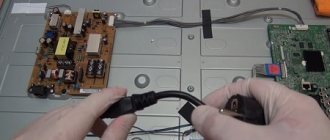
It is possible that the Samsung TV turns on itself due to interruptions in the power supply to the inverter. After all, even minor damage to a microcircuit or microcontroller will provoke voltage surges in the power system. Hardware repairs of modern TVs are best left to specialists. Service center engineers will use an oscilloscope to “ring” the contact circuit, which will eliminate the negative consequences of a short circuit.
How to disassemble
Repairing the Samsung Smart TV remote control begins with disassembling it.
For this job you will need some tools:
- a screwdriver with a Phillips head of a suitable diameter to match the size of the fastener on the remote control;
- flat screwdriver;
- knife;
- a plastic card.
The disassembly process includes a number of steps:
- We carefully inspect the device, studying the location of the fasteners . In many cases, some of the screws are concentrated in the battery compartment. Many people forget about them when trying to open the structure, which leads to its damage.
- Using a screwdriver of the appropriate size, unscrew the fasteners .
- We examine the joints for the presence of glue . If the adhesive layer is exposed, the edges of the case will have to be pryed off with a knife or a flat-edged screwdriver. You need to act carefully so as not to damage the plastic. A few precise movements and the two halves of the remote control will separate.
- Using a plastic card, you need to run it along the joints (you shouldn’t use a valid bank card, a card from a store is better for this), which will allow you to stretch the plastic and expand the hole.
- Carefully remove the battery contacts , which are located in the mounting grooves.
- Now you need to study the principle of attaching the board to the back cover . Screws or latches may be used. The screws are simply unscrewed with a screwdriver, and the latches need to be carefully picked up.
- The infrared diode can be fixed in the mounting socket - it must be carefully removed so as not to damage anything.
- The buttons can be removed from the remote control - just press them on the front side. The microcircuit is also unscrewed very carefully. The sensor does not need to be removed.
This completes the disassembly process. Then you can do cleaning and repair work.
How to open the touchpad remote
Not long ago, Samsung began producing remote controls with a touch panel. Despite the wider functionality and differences in the device, such designs are disassembled in the same way as conventional models.
The touch sensor does not pose any problems with disassembling the remote control.
The main point concerns the train, which you need to be careful with.
The cable connects the touchpad to the board. We take out all the parts from the plastic case, clean it, and then proceed to repair the product according to a single scheme.
Repair features
Problems may arise with a new remote that may not seem to work. The solution to this situation may involve several actions:
- First you need to make sure that the device is suitable for your TV model. This information may be contained in the operating instructions or on the manufacturer's official website.
- After checking the compatibility of the TV and the remote control, you need to remove the batteries and insert them back.
- You can also disconnect the TV from the power supply, and after a few minutes insert the plug back into the outlet.
A common problem is poor button operation. The reason for this behavior of the remote control is severe contamination or spilled liquid.
Let's consider how to act in such situations:
- Let's disassemble the remote control . Using a lint-free cloth soaked in alcohol, wipe the dirty areas.
- It will be more difficult to remove contaminants from the microcircuit - you need to be careful here . Excessive pressure or careless action will render the fragile part inoperative.
- Don't forget about the contacts in the battery compartment. They also need cleansing . Some people use sandpaper for this purpose. Experts do not recommend practicing this method.
- After removing dirt, the disassembled remote control should be left to dry for a day . After this, you can assemble it and check for functionality.
During operation, the remote control may be subject to mechanical damage - impacts and falls. The result of such situations are cracks and contact failures. Thin cables are used to connect microcircuits. You need to check each board and solder those that were damaged.
Mechanical wear is a common problem for all devices. In remote controls, the conductive layer under the buttons most often wears off. You can solve this problem yourself by restoring the conductive coating.
For this work, you can purchase a special kit or use regular foil.
Remote controls with a touch panel are worth talking about separately . The most common problem is the increase in battery drain rate. Over time, the remote control stops working even with new batteries. This problem is associated with a malfunction of the capacitors, which are located at the positive input. The solution to the problem is simple - just remove the capacitors.
In this form, the remote control will work normally, but the safety of its use is questionable.
If the touch panel malfunctions, you need to calibrate it. It is performed as follows:
- The batteries in the remote control are replaced, their type is indicated under the cover;
- Hold the Guide button for 5 seconds;
- calibration has been completed - you can check the operation of the touch panel;
- If the touchpad still does not respond, you need to reconnect the remote control.
Non-working buttons
There are often situations when the “Power” button located on the front panel of the TV gets stuck and cannot be pressed. This occurs as a result of mechanical damage. Sometimes a key is pressed but does not work. Most likely the cable was damaged. Be sure to check the functionality of the button. Because problems with it can cause the TV to turn on spontaneously.
The damage can be corrected by replacing the key. Users may have problems with this. First, you need to purchase a button that will fit your TV model. Secondly, the broken key must be carefully removed, and then a new one must be connected. To do this you need tools and skills in carrying out such work. Therefore, if you are unsure of your abilities, then contact the service center.
Prevention measures
In order for the remote control to last as long as possible and require repairs less often, it needs proper care.
Following simple rules will extend the life of your TV remote:
- The device requires periodic cleaning , the frequency of which depends on the intensity of use and the conditions under which it takes place. To clean the remote control, use alcohol-containing liquid, paper napkins, and toothpicks for cleaning hard-to-reach places.
- To make it easier for you to reassemble the remote control, when unscrewing it, all parts and fasteners must be folded in the appropriate sequence . There should be no unnecessary objects on the work surface - only parts and tools.
Ingress of moisture and dust
Dust and moisture deposited on the surface of microcircuits can lead to short circuits, as a result of which the basic hardware modules burn out. Therefore, it is necessary to adhere to the rules of equipment care in order to maximize its service life. For example, moisture gets in because many users spray cleaning products on the screen. You can't do this. Spray the liquid onto a dry cloth or microfiber, and only then wipe the screen.
Absolutely all devices need regular cleaning from dust. Televisions are no exception to this rule. It is possible that the TV turns off and turns on randomly due to dust settling on the microcircuits. Accumulations of dirt conduct current. Therefore, they are a catalyst for the appearance of sparks. As a result, a short circuit occurs. To clean the equipment from dust, remove the back cover, and then carefully blow out the dust using a vacuum cleaner.
What to do if the touch panel on the remote control for a Samsung F-series TV does not work
This article will help you fix the touch remote control for your F-series TV. If a similar problem occurs with a TV remote control of a different series:
1) Change the batteries.
2) Connect the remote control to the TV again.
Calibration for accurate touchpad performance
If the touch panel on the remote control does not respond well to touch, calibrate it:
On the subject: how to connect a touch remote control to a Samsung F-series TV
Can't find the information you need? We will help you.
Online
Consult a technician online
You can receive a response within 24 hours for general information or technical support
Leave a complaint or suggestion
Phone call
Kazakhstan, Uzbekistan, single support service from a mobile phone
Kazakhstan - to all telecom operators 24 hours / 7 days a week in Russian Mon-Sun, from 10:00 to 22:00 in Kazakh
Uzbekistan - Ucell, UMS, Beeline 24 hours / 7 days a week in Russian Mon-Sun, from 10:00 to 22:00 in Uzbek
There may be technical difficulties when calling from Beeline.
Kyrgyzstan, unified support service from a mobile phone Mon-Sun, from 10:00 to 01:00 in Russian Mon-Sun, from 10:00 to 22:00 in Kyrgyz
Tajikistan, single support service from a mobile phone Mon-Fri, from 09:00 to 00:00 in Russian Mon-Fri, from 09:00 to 21:00 in Tajik
Mongolia, unified support service Mon-Fri, 9:00 - 18:00 Sat, 10:00 - 14:00
8 100
Kazakhstan, single support service from a landline phone 24 hours / 7 days a week in Russian Mon-Sun, from 10:00 to 22:00 in Kazakh (Nur-Sultan time)
*For printer information, visit the HP website.
Source
Features of Smart Touch Control
The remote control for Samsung TVs with the Smart TV function, among other things, has a hydraulic sensor - a motion sensor. Thanks to it, you can control the TV by moving the remote control. In order for the cursor to appear, just touch the touchpad. Then it will move in accordance with the movement of your hand.
Examples of breakdowns due to which the TV remote control does not work
Replacement of the original driver - in this case we will receive a manufacturer approved remote control. Small differences from the original are cosmetic, not functional, and therefore a different shape or color, or a slight change in the layout of the controls does not cause a big problem when the toilet is trained to move the finger during operation. We offer replacement sellers, especially for older models or equipment that have made this amount to be financially attractive to manufacturers to promote the production of original drivers.
Disable HDMI Device Link
The secret behind this feature is hidden in the “Activate HDMI Device Link” option, which you will find in Settings > System > HDMI , and that the moment you disable it, any interaction with your TV or other device connected via HDMI will be eliminated.
This will avoid the problem of the console turning on by itself every time you turn on the TV, but you will also lose the opposite effect, so you will have to turn on the TV manually every time you want to play. First world problem.
Connecting Smart Touch Control
| Series F (2013) | Series H (2014) | Series J (2015) | Series K (2016) |
|
|
|
|
It has a touch surface and is used to change channels, mute the sound or read menu details. The touchpad, however, is larger. This is even known from touch laptops - so just swipe the center of the remote to move the cursor on the TV screen. The touch acts like a click. A new pilot can successfully replace the mouse's primary operation. It is used intuitively and conveniently. And if we are used to the traditional pilot, we will find it in the package with the TV.
When using a modern TV on a daily basis, it is also useful to accurately recognize gestures. A cursor will then appear on the screen, which you control by moving your hand. Clenching your hand into a fist will select the menu. When we wave on the movie screen, it adjusts to gestures using large buttons. It was also very interesting to use gestures in games.
When connecting for the first time, it is advisable to keep the remote control no more than 50 centimeters from the place where the signal is received.
Electrical chassis adjustments KS2A
To make electrical adjustments, the following equipment is required:
- digital multimeter;
- kilovoltmeter;
- television signal generator;
- color spectrum analyzer, for example, CA-100.
Before adjusting the TV, turn it on and let it warm up for 15...20 minutes. If colored spots appear on the screen (color purity is impaired), demagnetize the kinescope using an external demagnetization loop.
High voltage control
On the KS2A chassis, the high voltage is not regulated, but only monitored. First, check the horizontal scan supply voltage: at the positive terminal of capacitor C815 there should be +125...135 V (depending on the diagonal of the kinescope). If the voltage deviation exceeds 10%, repair of the power supply is necessary.
If the IP is working properly, connect a kilovoltmeter to the second anode of the kinescope and turn on the TV. The high voltage should be 30 ±0.5 kV at any brightness and contrast values. If it does not correspond to the above value, the TV needs to be repaired.
Table 1
| CRT diagonal, inch | Options | |||
| IBRM | WDRV | C.D.L. | COLR G V (Smallest Value) | |
| 21 (PF/TOSHIBA) | 220 | 35 | 180 | 65 |
| 21 (1.7R/SDI) | 220 | 35 | 180 | 100 |
| 22.25 (1.7R/SDI) | 220 | 35 | 200 | 150 |
| 15 (PF/SDI) | 220 | 35 | 180 | 100 |
Focus adjustment
A black-and-white signal is supplied to the antenna input of the TV from the test signal generator, the best image quality is achieved by fine-tuning the tuner, and the focus of the image in the central part of the screen is adjusted with the F0CUS1 regulator on the TDKS (T444S).
Adjusting the voltage on the kinescope modulator
- A “vertical color stripes” signal is supplied to the antenna input of the TV.
- Enter the service mode (see below), select the G2-AD-JUST position and set the values of the parameters IBRM, WDRV, CDL and COL G B in accordance with table. 1.
- Rotate the SCREEN knob on the TDKS (T444S) and control the color of the image of the MRCR GB and MRWDG parameters (see Table 8). If the inscriptions change color from green to red, then the voltage value on the kinescope modulator is not normal.
A green color is achieved for the images of the MRCR and MRWDG parameters.
Replacing the IC902 non-volatile memory chip (EEPROM)
If the EEPROM chip needs to be replaced, the original adjustment data must be written to it. This operation is performed as follows:
- After replacing the EEPROM chip, the TV is turned on.
- The TV will switch to standby mode. It is necessary to leave it in this mode for at least 10 seconds.
- Switch the TV to operating mode from the remote control or from the front panel
.
After this, the original adjustment data will be automatically written to the EEPROM.
Adjusting White Balance
For this operation, it is advisable to have a color spectrum analyzer (the manufacturer recommends the CA-100 model), but you can do without it, although the adjustment will be more accurate with the device.
- Select the STANDARD picture mode from the TV OSD menu.
- Apply a “white field” signal to the input and allow the TV to warm up for at least 30 minutes.
- Enter the service mode and select the VIDEO ADJUST1 position.
- Select the SUB CONTRAST parameter and set the brightness value Y=65±0.3.
- Use the RED DRIVE and BLUE DRIVE parameters to set the analyzer readings x=265, y=265.
- Select the SUB CONTRAST parameter and set the brightness value Y=1.2±0.3.
- Use the RED CUTOFF and BLUE CUTOFF parameters to set the analyzer readings x=265, y=265.
- To move from one parameter to another, use the CHANNEL UP/DOWN buttons, and to adjust parameters, use the VOLUME +/- buttons.
Without a color spectrum analyzer, white balance is adjusted using the same parameters, first at near maximum brightness (90%) and then at minimum brightness, when the screen is barely lit. Adjustment quality control is visual.
Note: Y, x, y values are for model 21PF. For other TV models, set these values in accordance with table. 2.
Service mode
To switch the TV from operating mode to service mode, press the buttons on the standard remote control in the following sequence: PICTURE OFF-DISPLAY-MENU-MUTE-PICTURE ON. The following image should appear on the screen (Fig. 1):
This means that the TV is in service mode. To select parameters, use the remote control or front panel CHANNEL UP/DOWN buttons, and to adjust parameters, use the VOLUME +/- buttons.
Rice. 1
table 2
| Region | CRT diagonal, inch | High brightness | Low brightness | ||||
| X | Y | Y(ft) | X | Y | Y(ft) | ||
| Southeast Asia | 21(PF) 21(1.7R) 15(PF) | 265 265 265 | 265 265 265 | 65 60 95 | 265 265 265 | 265 265 265 | 1,2 1,5 2,0 |
| Near East | 21(PF) 21(1.7R) | 290 290 | 300 300 | 65 55 | 290 290 | 300 300 | 1,2 1,5 |
| CIS | 21(PF) | 272 | 270 | 65 | 265 | 266 | 2,7 |
After repairing (replacing) the picture tube, picture tube board, TDKS, EEPROM chips and IC901 microcontroller, be sure to adjust the parameters of all items in the service menu. The RESET position is used to assign all parameters to their original (factory) values. After all parameters have been adjusted, turn the TV off and on again using the power switch. The new values will be stored in the non-volatile memory chip.
Table 3
| No. | Screen image | Parameter description | Adjustment range | Factory value | Note |
| 1 | V Shift | Vertical shift | -128…127 | -54 | — |
| 2 | V Amp | Vertical size | -128.127 | 15 | |
| 3 | V Stope | Vertical tilt | -T28…127 | -2 | |
| 4 | VSC | S-correction | -128…127 | -15 | |
| 5 | H EW | Horizontal size | -128…127 | 6T | |
| 6 | H Trapezium | Trapezoid horizontal | -128…127 | -8 | — |
| 7 | H Parabola | Parabola horizontally | -128…127 | -z | _ |
| 8 | H Symmetry | Horizontal symmetry | -128..127 | 12 | |
| 9 | H Corner | Distortion in the corners | -128..127 | -32 | — |
| 10 | H Shift | Horizontal shift | -128.127 | 10 | — |
| 11 | PIP Contrast | PIP Image Contrast | 0.15 | 0 | Parameters for adjusting the PIP image |
| 12 | PIP Tint | PIP Image Color Tone | 0…63 | 0 | — |
| 13 | PIP H.Move | Horizontal offset PIP | 0…7 | 0 | |
| 14 | PIP V. Move | Vertical offset PIP | 0…7 | 3 | |
| 15 | PIP PAL V.Pos | PIP vertical offset in PAL system | 0…255 | 33 | _ |
| 16 | PIP NTSC V.Pos | PIP vertical offset in NTSC system | 0…255 | 33 | |
| 17 | PIP NTSC V.Pos | Horizontal centering of the PIP image | 0…255 | 42 |
In table 3 shows the parameters, their adjustment range and the factory values of the DEFLECTION service menu item.
Table 4
| No. | Screen image | Parameter description | Adjustment range | Factory value | Note |
| 1 | Red Cuffoff | Red cutoff | O…255 | 127 | Used to adjust white balance in dark |
| 2 | Green Cutoff | Green cutoff | 0…255 | 127 | — |
| 3 | Btue Cutoff | Blue Cutoff | 0…255 | 127 | — |
| 4 | Red Drive | Red Gain | 0…255 | 127 | Used to adjust white balance in highlights |
| 5 | Green Drive | Green Gain | 0…255 | 127 | |
| 6 | Blue Drive | Blue Boost | 0…255 | 127 | — |
| 7 | Sub Bright | Subbrightness | 0…200 | 100 | White balance in dark |
| 8 | Sub Contrast | Subcontrast | 0…63 | 52 | White balance in light |
| 9 | Sub Color | Subcolor | 0…27 | 27 | Parameters are not adjustable |
| 10 | Sub Tint | Subtone | 0…100 | 30 | — |
| 11 | BCL Threshold | Adjusting the current limit of kinescope beams | 0…255 | 77 | — |
| 12 | BCL Gain | — | 0…15 | 8 | — |
| 13 | BCL Time | — | 0…15 | 13 | — |
| 14 | TXT Contrast | Image Contrast OSD/TXT | 0…255 | 90 | — |
| 15.. | YC Delay | Y signal delay | 0…8 | 3 | — |
In table Figure 4 shows the parameters with the adjustment range and the factory values of the VIDEO ADJUST 1 service menu item.
Table 5
| No. | Screen image | Parameter description | Adjustment range | Factory value |
| 1 | In stretch-BTHR | Black Level Enhancement Threshold | 0…55 | 50 |
| 2 | In stretch-BTLT | Black level expansion | 0…15 | 8 |
| 2 | B stretch-YOU | — | 0…31 | 4 |
| 4 | Coring | Peak Brightness Filter | 0…31 | 31 |
| 5 | RGB Light | External RGB brightness | 0…255 | 0 |
| 6 | RGB Contrast | External RGB signal contrast | 80 | 0 |
| 7 | EHT Time | High voltage circuit sensitivity | 0…15 | 0 |
| 8 | EHT Compensation | High voltage compensation | 0…255 | 60 |
In table Figure 5 shows the parameters, their adjustment range and the factory values of the VIDEO ADJUST2 service menu item.
Table 6
| No. | Screen image | Parameter description | Adjustment range | Factory value |
| 1 | Peak Threshold | White Level Threshold | O…255 | 255 |
| 2 | Soft Limit Slope B | Image clipping levels | 0…15 | 2 |
| 3 | Hard Limit | 0..255 | 255 | |
| 4 | Peak Video Ref | Reference white level | 0…4 | 0 |
| 5 | Pead Video Gain | Video gain threshold | 0…5 | 0 |
| 6 | ACC-REF (PAL/NTSC) | Automatic color adjustment in PAL/NTSC systems | 0…20 | 20 |
| 7 | ACCR(SECAM) | Automatic color adjustment in SECAM system | 0…39 | 21 |
In table Figure 6 shows the parameters, their adjustment range and the factory values of the VIDEO ADJUST3 service menu item.
Table 7
| No. | Screen image | Parameter description | Adjustment range | Factory value |
| 1 | MRCRGB | Initial cut-off levels | No Control | 110 110 110 |
| 2 | MRWDG | Initial gain level G | No Control | 110 |
| 3 | IBRM | — | 0…255 | 220 |
| 4 | WDRV | White gain value | 0…255 | 35 |
| 5 | C.D.L. | Level at cathodes | 0…255 | 180 |
| b | COL RG B | Cutoff levels | O…255 | 65 70 75 |
In table Figure 7 shows the parameters, their adjustment range and the factory values of the G2-ADJUSTMENT service menu item.
Table 8
| Item no. | Screen image | Parameter description | Adjustment range | Factory value |
| 1 | VSU | Setting the vertical delay | 96…111 | 108 |
| 2 | HQEW | EW data for PLUS screen mode | -30…30 | 0 |
| 3 | H Zoom Parabola | Parabolic correction for ZOOM screen mode | -15…15 | 8 |
| 4 | H 16:9 Parabola | Parabolic correction for 16:9 screen mode | -15…15 | -18 |
| 5 | TXT Position | Teletext horizontal shift | -30…30 | 0 |
| 6 | Mono Sound System | Selecting the sound standard DK I M | B.G. | B.G. |
| 7 | V Slice level | Personnel SI level | 0..3 | 2 |
| 8 | Melody Volume | Melody volume | 0…20 | 5 |
In table Figure 8 shows the parameters, their adjustment range and the factory values of the G2-ADJUSTMENT service menu item.
Possible malfunctions and ways to eliminate them
The TV does not turn on, the mains fuse F801A has blown
Break the circuit between the positive terminal of capacitor C806 (pin “B” of the diode bridge D801S) and pin. 1 transformer T801S. Then, using an ohmmeter, check the elements of the VX801VP801S CX801S CX802S LX801S LX8O2S line filter, the D801S C806 rectifier, and the P801S LC801S demagnetization circuit for short circuits.
If no faulty elements were found during the check, then restore the broken circuit and check the IC801S microcircuit and the C807 capacitor. Most often, the key transistor that is part of the microcircuit fails (source - pin 2, drain - pin 1). The cause of fuse F801A blowing in the event of a failure of the current protection system (inside IC801S) may be a short circuit in the secondary circuits of the power supply due to the failure of one of the elements of the output rectifiers, integrated voltage stabilizers IC803-IC805 and other consumers. An ohmmeter is used to determine which circuit has a short circuit and eliminate the cause.
The TV does not turn on, the mains fuse F801A is working, the LED on the front panel of the LD901 does not light up
The performance of the IP can be determined by the presence of signals at the control points TPO1 and TPO2. If there are no signals, then the IP is faulty and requires repair.
A voltmeter is used to monitor the voltage (about 300 V) at the positive terminal of capacitor C806. If it is missing, use an ohmmeter to check the elements of the mains filter, rectifier, and the quality of their soldering for breaks.
Then use an ohmmeter to check fuses NT801S and NT802S, windings 1-2 and 3-4 of transformer T801S. After identifying and replacing the faulty element, the functionality of the IP converter is checked (see oscillograms TP01 and TP02). This is the only way to check its performance, since in the event of a short circuit in the power supply loads, its output voltages are close to or equal to zero. If there is a voltage of 300 V at the pin. 11C801S, and the TP01 signal is missing, check the start circuit R802 R803 R804 D801 and the elements that provide power to the microcircuit in operating mode: winding 8-9 T801S, D803, C808. If they are working properly, check elements DZ801, C803, C809, R825, DZ802, DZ808, D804. If these elements are in good condition, replace the IC801S chip.
If the IP converter is working, check the power supply to the IC901 MK (3.3 V on pins 11, 33 and 2.5 V on pins b, 13, 37 and 42). If there is no power, then check winding 14-13 T801S, as well as elements FD803S, D806, C818, R828, IC804, C832, D810, IC903, C917, C918.
If the MK's power supply is normal, check its external elements: IC904, IC902 (replacement only), X901 (5 MHz). If they are serviceable, replace the MK.
The TV does not turn on, the LED on the front panel of the LD901 is lit
First, check the I2C digital bus signals on the pin. 5 and b IC901 (see oscillograms TP26, TP27). If one or both signals are missing, one of the transistors Q909, Q910 may be faulty.
Often, for various reasons, the recorded information in the IC902 memory chip is destroyed. Its verification consists of replacing it with a working copy.
If I2C bus signals are available, check the low level of the POWER signal at pin. 50 IC901, open state of key Q908 and performance of stabilizers IC803, IC805. On the pin. 50 IC201 should be horizontal scan trigger pulses. If they are not there, check the power supply of IC201 (5 V at pins 15, 36, 53 and 58) and the quartz resonator X201. If there are pulses, check the operation of the Q222 buffer (TP08 oscillogram) and the horizontal scanning circuit on elements Q402, T401, Q401, T444S. To check the horizontal scan, control the supply of 135 V supply voltage through winding 1-3 of T444S to the collector of transistor Q401 and 12 V through the primary winding of T401 to the collector of Q402. Check the passage of lowercase trigger pulses through the circuit: pin. 50 IC201 - Q402 - T401 - Q401 (see oscillogram TPO6).
If there is no 135 V voltage at the Q401 collector, check the 135 V channel of the power supply, fuse FD401S and winding 1-3 of T444S.
The TV turns on and immediately after the appearance of high voltage switches to standby mode
Typically, this defect is associated with the inclusion of X-Ray Anti-Ray (X-RAY) circuitry. The circuit detector based on elements RR01S, RR07S, DR01S, CR01S, CR02S, DZR01S, QR01S, CR03S controls the amplitude of voltage pulses on the 6-7T444S winding. To verify this, monitor the voltage at the pin. 23 IC901. If, after switching on, the voltage at this pin becomes zero, the X-RAY circuit is turned on. First of all, check the voltage at the output of the 135 V channel. If it is significantly higher than the norm, the cause of this is eliminated. If the IP is working, check the elements of the horizontal scanning circuit, first of all CR401S-CR403S, D409, T444S.
If the voltage on the kinescope channel is no more than 6.5 V, then the elements of the X-RAY circuit itself are faulty.
There is sound, no image and raster
Check the glow of the kinescope. If it does not light up, check its power supply circuit: pin. 7 T444S - R405 - CN502 - R522 -R523 - heater - housing. If there is power, replace the kinescope.
Then check the presence of voltage on the kinescope modulator. If the raster appears by turning the SCREEN knob on the T444S transformer, check the supply of RGB video signals to the cathodes of the kinescope. If they are not there, check for the presence of signals on the pin. 37-39 IC201, their passage through amplifiers Q202 Q207 Q210, Q203 Q209 Q208 and Q204 Q213 Q206 to the kinescope board. On the board, first check the supply voltage of 215 and 16.5 V to connector CN502. These voltages are generated by a horizontal scanning circuit. If the power supply is normal, check the video output amplifiers IC501-IC503.
There is a picture, no sound
First, check for the presence of signals at the outputs of the UMZCH - pin. 1.2 and 14.15 IC602. If they are, then check the connectors CN601, CN602 and dynamic heads. If there are no sound signals, check the TV-AUDIO (MONO-AM) signal at pin. MONO tuner TU01S and its passage through the circuit: pin. 7, 8 IC603 - pin. 4, 5 IC603 -С612, С613 — pin. 4.12 IC602. MUTE signal to pin. 49 IC901 should have a low level and on pin. 6 IC602 should also be low (mute disabled). Before replacing microcircuits through which the signal does not pass, check the presence of supply voltages on them.
There is a raster, there is no sound and image, the OSD menu is displayed
First, the I2C bus signals are checked (see oscillograms TP26 and TP27). If there are no signals, check the memory chip IC902 (by replacement), external elements of IC901 and the MK itself.
If there are digital bus signals, check their arrival at the TU01S tuner. Then they control the tuner’s power (5, 8 and 33 V at the corresponding pins) and use the on-screen menu to turn on the automatic program tuning mode (don’t forget to connect the antenna!). If, as a result, you cannot tune in to any program, then replace the tuner.
There is no control of the TV from the remote control
First, check the serviceability of the remote control. Using a thin screwdriver (awl), carefully separate the halves of the remote control housing and check the integrity of the printed circuit board and the elements installed on it, as well as the spring contacts from the batteries at the place where they are soldered.
Assemble the remote control and check the serviceability of the batteries. Then they connect an infrared photodiode (FD-24 and similar) to the oscilloscope, point it at the remote control photodiode, press any buttons on it and control the presence of packets of control pulses on the oscilloscope screen. Their amplitude should be about 0.1...0.2 V.
If pulses are received from the remote control, check by replacing the remote control quartz resonator. If it is working, check the elements in the control signal circuit in the TV: from the photodetector RM901 through R921 to the pin. 24 IC901 microcircuits (see TRZO oscillogram). If there is a signal, replace the MK.
One of the primary colors is dominant or absent on the TV screen
If the white balance is off, adjust it in service mode. If it is not possible to adjust the image, check the presence of primary color signals and their amplitude (about 1 V) at the outputs of the IC201 microcircuit (pin 37-39) and then along the entire video path to the cathodes of the kinescope. A section of the circuit is determined where one of the signals is missing or its amplitude is significantly less than that of other signals, the cause is determined and eliminated.
If the comparative range of the R, G, B signals is the same along the entire path of their passage, then the kinescope is most likely faulty.
No color image
Check the color saturation setting in the OSD menu, it may be at the minimum position. Then, if the color does not appear, enter the service mode and check all parameters related to color. If everything is normal, but there is no color image, then replace the IC201 chip.
The top or bottom half of the image is missing from the screen
Check the power supply of the vertical scanning chip IC301 (16.5 V on pin 6 and -16.5 V on pin 1). If one of the voltages is missing, check the corresponding sources:
- 16.5 V: exchange. 6-8T444S, R425, D401, C402, pin. 6 IC301;
- -16.5 V: exchange. 9-10 T444S, R424, D402, C404, pin. 11C301.
If the power supply is normal, replace the IC301 chip.
The raster is distorted vertically, the size is too small or large
First, enter the service mode and adjust the corresponding parameters in the Deflection menu. If there is no result, check the compliance of the VDP signal (pin 31 001) with the TP09 oscillogram. If the signal does not correspond to the one shown, check the power supply of the IC201 microcircuit for the absence of ripple. If the power supply is normal, check the IC201 chip by replacing it.
If the VDP signal is normal, check the power supply of the IC301 chip in the same way, then check the capacitors C301, C302, C307 by replacing them. If there is no result, replace IC301.
The TV does not work in teletext mode
The teletext functions on this chassis are performed by the IC901 MK. Turn on the teletext mode and check the presence of a TTX CVBS video signal with a swing of about 1 V at the emitter Q201 and its arrival through the emitter follower Q901 to the pin. 12 IC901. If there is a video signal, but on the pin. 37-39 IC201 there are no teletext signals - they replace the MK.
If there are teletext signals at the outputs of IC201, check their passage through the H002 module “frame in frame” (input - pin 13-16 CNP02, output - pin 9-12 CNP01) to the input of the multifunctional microcircuit IC201 (pin 41-44) . If teletext signals arrive at the input of IC201, replace this chip.
Schematic diagrams and oscillograms of signals at control points of SAMSUNG TVs on the KS2A chassis can be downloaded here.
Magazine "Repair & Service"
If you can't configure
If you are unable to set up Samsung Smart Touch, try the following:
- Make sure the batteries are charged. If this is not the case, a warning will appear on the screen.
- Remove and reinsert the batteries. Make sure they are positioned correctly.
- Unplug the TV and turn it on again.
- Make sure that this is the remote control for this TV.
- Try setting up the remote control again.
Use your smartphone or tablet as a remote control! Additional control of the TV gives us another smart device, smartphone or tablet. When connected, you can not only watch movies or photos on the big screen, but also use all the options of your smartphone. We can not only change channels and control individual functions, but also write text from a smartphone. It also allows you to watch a different channel on your smartphone or tablet screen than the one you currently see on your TV screen.
PS5 always turns on with TV
If you're one of the lucky ones who has a brand new PS5 at home, you've probably encountered the following problem. You turned on your Smart TV to watch Netflix or browse YouTube, and the PS5 automatically turns on when exactly you weren't going to play on the console at that moment. Why is this happening?
Full repair of Smart TV and remote controls
However, even such equipment breaks down and is prone to failure. If a problem occurs with your SMART TV, you do not need to try to remove the problem yourself. Only TV professionals can help you in this matter!
Our company “REMONT-TVV” works with many brands: Loewe, Philips, Samsung, LG, Sony, Metz, Rolsen, Panasonic, Toshiba, Thomson, Mystery, Bravis, Sharp, Pioneer and promptly carries out repair work, in everything with high quality and inexpensive prices. We save the client’s time and desire to receive working equipment.
Following the steps above, you come to the conclusion that the problem is with the remote control, so try to get it back together. First, carefully open the battery cover and try to remove it from the remote control. If you don't, try shaking the remote a few times while holding it with your right hand and pointing the battery compartment face down into the palm of your left hand. Old and worn-out batteries can leak into the remote control, causing oxidation of metal contact parts or internal electronic components, often rendering the remote control unrepairable.
Call, write. We'll come and fix everything. We can handle absolutely all breakdowns:
SMART TV does not turn on - the indicator does not light up; . the red indicator does not respond to the remote control and the TV does not turn on; . after turning on, the green indicator lights up for a couple of seconds, then turns red or goes out; . after turning on, the screen freezes with a static picture without sound; . after turning on, the screen freezes with a static picture with sound; . malfunctions associated with failures of sounds and pictures, etc.
Our advice is to always use new quality batteries that have the words “Alkaline Batteries” written on them. These batteries have a slightly higher price, but are justified by their increased lifespan compared to regular batteries, they do not leak after consumption and are not recyclable. Returning, if the batteries work on the remote control, you should clean the waste fluid from the batteries with a dry cloth, insisting on the electrical contacts that you want to clean, then using a fine abrasive material with a gloss or a sharp point of the object more severe.
Our company will repair SMART TV TVs at home in Moscow and the Moscow region
. We have been working for several years now. During their fruitful work, telemasters have won the trust and respect of clients throughout the district. They trust us! Our work is appreciated! Take advantage of the high-quality services of masters now.
Source
When do you need a new remote control?
If the TV does not respond to pressing the remote control buttons, first of all you should check the batteries and, if necessary, replace them, and then you need to make sure that it is not blocked (by accident or from children).
If these reasons are not related to the problem, then it is deeper - at the hardware level. On a note! You can learn about ways to put the remote control into working condition from the instructions or consult with specialists in the repair of consumer electronics.
If all measures to resolve the problem do not help, the right solution would be to purchase a working remote control. The same should be done if the device is destroyed (for example, due to a fall from a height), after it is completely immersed in liquid for a long time, as well as if the microcircuits overheat and melt due to exposure to high temperatures. Complete restoration of such a device can take a long time and cost an amount equal to the price of a new device.