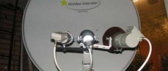
Setting up a satellite dish - theory. Satellite TV frequencies.
Frequency is usually divided into so-called ranges (or sub-ranges), which are assigned their own designations.
That is, the signal coming from the satellite has a certain frequency, which in turn falls within the framework of the so-called frequency ranges. To receive satellite television broadcasts, two frequency bands are mainly used: C and Ku. There are, of course, others, but you are unlikely to meet them, so I will not dwell on them.
To understand what these ranges are, let’s look at a simple example, as always.
Let's imagine a car driving down the road. Let's assume that while driving, its speed changes from 10 to 100 km/h. Now let's divide our speed into ranges. For example, in the first range, this speed will change from 10 to 49 km/h, and in the second, from 50 to 100 km/h. This is where it turns out that the car changes its speed in two, let’s call them low and high, ranges.
The satellite signal is also divided into the same ranges, only radio frequencies. For example - C band (C Band), or Ku band (Ku Band). Below is a table of broadcast spectrum frequencies:
C - band - used on relatively old satellites. Ku - band, more popular for direct satellite broadcasting. Approximately 95...98% of viewers watch TV programs there.
Explanation: Some terms placed further on the pages will not be clear to you; to study each one separately will require a lot of time and effort from you, and some initial preparation is required. And it may happen that not everyone will read this topic to the end. Whatever happens, we will do it easier. I will highlight unfamiliar words in red, but you just need to remember them. There are not many such words here, so I think this will not be difficult for you. In any case, if you forget, you can always go back and go over the already familiar words again.
(types of satellite signal polarization)
In addition to the frequency spectrum (range), satellite signals differ in the type of signal polarization. Here are the main types of signal polarization you may encounter:
1) Linear horizontal - abbreviated “H” (Horizontal).
2) Linear vertical - abbreviated as “V” (Vertical).
1) Circular right - abbreviated “R” (Right).
1) Circular left - abbreviated as “L” (Left).
Horizontal polarization signal (Horizontal) - goes to the satellite antenna in the horizontal plane (Fig. 1).
Rice. 1 Horizontal polarization signal - Horisontal (H).
The vertical polarization signal (Vertical) is in the vertical plane (Fig. 2).
Rice. 2 Vertical polarization signal - Vertical (V).
In circular polarization (Circular) - the signal seems to rotate in one direction or the other at a very high speed, conventionally called right - Right (R), and left - Left (L) polarization.
…
Now, we will figure out what main types of converters are used to receive satellite signals.
Further…
Everything about the Starlink Satellite Internet project. Part 21. SL and polarization problems
I suggest you familiarize yourself with previously posted materials on the Starlink (SL) project:
Part 1. Birth of the project
‣
Part 2. SL network
‣
Part 3. Ground complex
‣
Part 4. User terminal
‣
Part 5. State of the SL group and closed beta testing
‣
Part 6. Beta testing and service for subscribers
‣
Part 7. SL network capacity and the RDOF program
‣
Part 8. Installation and activation of the subscriber terminal
‣
Part 9. Service in markets outside the USA
‣
Part 10. SL and the Pentagon
‣
Part 11. SL and astronomers
‣
Part 12. Problems of space debris
‣
Part 13. Satellite network latency and access to radio frequency spectrum
‣
Part 14. Intersatellite communication channels
‣
Part 15. Rules for the provision of services
‣
Part 16. SL and weather
‣
Part 17. Second generation SL
‣
Part 18. SL in the COTM market
‣
Part 19. What's in the future for SL
‣
Part 20. Internal structure of the SL terminal
First, a little theory...
If we are talking about a radio wave, then it has such a characteristic as “polarization”. It is described in words like this:
Wave polarization is a characteristic of transverse waves that describes the behavior of the vector of an oscillating quantity in a plane perpendicular to the direction of wave propagation.
Understanding words is much more difficult than seeing it in a picture:
Above is circular polarization, below is vertical (blue line) and horizontal (red line).
For satellite communications, vertical/horizontal or left/right circular pairs are used. What are the benefits of polarization? And the fact is that it allows you to DOUBLE the used frequency range, if in our Ku band, according to the frequency distribution from the International Telecommunication Union aka ITU), you can use only 500 MHz (from 14000 to 14500 MHz), then if we use 2 polarizations, we can already have 500 MHz in each and we will get a total of 1000 MHz. For example, on the Yamal-200 satellite in the Ku-band there were only 6 transponders of 72 MHz, operating only in 1 polarization, and on Yamal-300K (which was supposed to replace Yamal-201 in the 90-degree position) there were 12 such transponders ( 6 in horizontal and 6 in vertical) and, accordingly, the income of the Operator (Gazprom Space Systems) from the sale of frequency resources doubled.
If we look at Starlink, they also understand the importance of this and, judging by the table below, in 2020 they stated to the FSS that they want to use both polarizations over the entire possible frequency range of 2000 MHz in right and left circular polarizations (Rx01 and Rx02 have the same frequencies, but different polarizations).
And then, with a spectral efficiency of 5 bits/Hz (very high, but theoretically achievable with very good antennas and a large Signal/Noise value), we obtain a throughput of one satellite of 4000 MHz x 5 bits/Hz = 20 Gigabits.
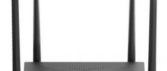
However, as always there is a BUT! Let's see how this is implemented... If we have a regular parabolic antenna, then the polarization is established by rotating the feed and its waveguide around the axis of the antenna:
//
In general, the polarization parameters are taken from the regulations of the company providing satellite resource rental services (for example, the RSCC regulations).
The polarization angle depends on the exact coordinates of the VSAT installation site and is determined in special programs. You can find it out from the NCC operator (Network Control Center, usually in Moscow) by providing him with the coordinates.
After the azimuth and elevation bolts are tightened:
Loosen the bolts on the transceiver mounting unit (ODU)
Rotate the ODU to the polarization angle obtained in the calculation program and perform the steps below.
After confirmation from the operator that the parameters meet the standards and the azimuth and elevation angle are adjusted normally, it is necessary to make additional polarization adjustments.
Polarization adjustment is performed in several stages:
- A representative of the installation team, under the direction of the control center operator, slightly loosens two bolts
- At the direction of the NCC operator, the installer begins to rotate the transmitter clockwise/or counterclockwise in increments of no more than one degree until the operator stops the adjustment.
- The installer tightens the bolts and cross-polarization measurements are taken again
- If it is not possible to achieve the required cross-polarization value, you will need to adjust the antenna in azimuth and elevation, and then repeat step 3 of this section.
And this is a very labor-intensive operation, especially when the installer sits on the roof in the cold, because it is almost impossible to “catch millimeters and degrees” in mittens, and communicates with the NCC operator via an Iridium satellite phone (1 minute = 1 dollar)... But the main thing is that polarization depends on the distance to the satellite and for phased array antennas (the angle of inclination of the beam relative to the antenna plane).
To be fair, it should be noted that for circular polarization there are no such difficulties; you just need to choose the right position of the diplexer, for which there are two options - Left and Right, differing by 90 degrees.
A diplexer is a passive device that implements multiplexing in the frequency domain. Two ports are multiplexed onto a third port. Signals on ports 1 (to the receiver) and 2 (to the transmitter) occupy non-overlapping frequency bands. Therefore, signals on 1 and 2 can coexist on port 3 (from the antenna) without interfering with each other.
Now let's get back to SL.
- First moment, phased array antennas have worse cross-splitting isolation than classical parabolic antennas. For parabolic antennas, the standard is 29..30 dB, and for headlamps, as professionals in this field told me, 26-28 dB is considered very good when working with a geostationary satellite and when the object is moving at speeds of 30..80 km/h...
- In the case when your distance to the satellite and the inclination angle are constantly changing at high speed, it is very difficult to adjust the cross-polarization isolation (CPI) with the required accuracy. Even parabolic antennas on sea vessels suffer from the fact that the CPR sometimes “flies” and the terminal begins to interfere with a channel in a different polarization. And the ship, as you know, moves a hundred times slower than the satellite.
Alas, none of the manufacturers of FAR ESA (Phased Electronic Beam Control) antennas have yet published data on real cross-field isolation when working with satellites in low orbit 500+ km.
In the case of Starlink, the problems with polarization are an order of magnitude more complex.
Here, phased array antennas are located at both ends of the satellite channel - both on the satellite and on the ground. In addition, not only the distance to the satellite changes continuously and very quickly, but also the angle of inclination of the beam relative to the antenna plane...
With all the genius, hard work and available budget of the engineers whom Elon Musk attracted to create his terminal, 2 years ago it seems to have become clear to them that it would not be possible to use two polarizations, and SpaceX sent an application to the FSS that its ground terminals would use only 1 (one) polarization – Right on the line from the satellite to the terminal and Left in the direction from the terminal to the satellite...
That is, SpaceX had to voluntarily give up 50% of the Starlink network capacity, which was allocated to it by the FCC for the operation of its user terminals...
We also note that in the Ka-band, which is used in Starlink to transmit information from Earth to space, this problem does not exist at all, since parabolic antennas are used both on the satellite and on Earth, for which the cross-field problem is solved by conventional methods, and from the gateway A total of 4000 MHz can still be transmitted to satellites in 2 polarizations...
Is it possible to fix something here in the future? Theoretically, it’s probably possible (especially since paper will tolerate anything, any fantasies...). But any decision here will affect the geometry, parameters, possibly materials and design of the terminal and its phased array. At the same time, we remember that the main goal is to reduce the cost of the terminal. And the terminal has already been designed and is in serial production...
What can be done?? To answer this question, information is needed about the actual size of the cross-polarization junction.
Unfortunately, while the Starlink terminal falls into the hands of more and more Locksmiths or IT specialists, who break it or look at what kind of Wi-Fi there is... No one has yet guessed (could not take the frequency characteristics of the terminal) at what frequencies it operates, what mod codes it has cross-field decoupling, what kind of interference it puts into the other polarization. These measurements are not easy - you need 2 spectrum analyzers at 14 GHz (once they cost tens of thousands of dollars, I won’t say how much now, but still not cheap), an electrically driven parabolic antenna, and a non-standard controller capable of tuning and tracking a signal of an unknown format (regular controllers tailored for the “television” signal format DVB-S2, but not the fact that it is used in Starlink) in order to simultaneously measure the signal from the satellite in both polarizations, but I hope that within six months, one of the satellite companies in the USA will will fulfill it, and the information will leak onto the Internet...
What are the possible options??
- If the interference in the other polarization is relatively small, use terminals with a high gain, for example: parabolic antennas with a diameter of 1 or more meters. In this case, the obstacle is simply to reduce the “working” modcode - work efficiency. For example, if SL uses sufficiently large electrically driven terminals for seas and oceans, then this problem will not be very critical there.
- In principle, do not use this polarization, but switch all possible resources available in the Ka-band of 4000 MHz to Ku, using frequency reuse or frequency reuse technologies:
What is frequency reuse? This technology is actively used in HTS (High Throughput Satellite) satellites. It’s enough to simply divide our 2000 MHz in one polarization into 4 ranges of 500 MHz (we’ll denote them with different colors)
(To be more precise, judging by the description of the terminal, the frequency range for Starlink is divided not into 4 colors, but into 8, since the channel from the satellite down has a width of 240 MHz and 8 channels will fit in 2000 MHz, but these are details. In In this case, each beam (spot, illumination zone on Earth) has its own frequency range, which does not overlap with another beam with the same frequencies, that is, there is no mutual interference.
And most importantly, in this case, Starlink can use all 4000 MHz that it transmits c/to Gateway satellite in Ka-band.
We cannot yet say what solution SpaceX chose: the ability to work simultaneously in 2 polarizations or abandoning one and using frequency reuse.
Indicating both polarizations in the frequency application filed with the FCC is simply an administrative and legal measure, so SpaceX reserved the right to use them and annulled the ability of other operators to file a complaint against it for the presence of broadcast interference in this polarization.
The answer to this question will be to know how many beams a satellite can simultaneously broadcast to Earth, 8 or 16 (or even more, because formally the antenna on a satellite can transmit narrower beams, not only 240 MHz wide, but also 120 MHz and 60 and 30 even 15 MHz).
There is no answer to the question whether such channel switching on satellites is possible in order to use all 4000 MHz, because if the answer is negative, the Starlink network will not be able to use half of the satellite resource available to it... And this situation, most likely, will not be corrected before the launch of new satellites generation (if we accept that it is generally theoretically and practically possible to create a phased array with a CPR at the level of 29..30 dB)... And half of the frequency resource for areas with high demand for Starlink services is half of the income...
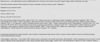
Satellite TV transponders from MTS
Frequencies and transponders of satellite TV from MTS.
Frequencies of MTS channels on the ABC-2 satellite:
| Channel name | LED | APID | VPID | Format | Sound. Track |
| 11740V Russia 53 DVD-S2 8PSK SR 45000 FEC 2/3 | |||||
| Home (+4h) | 1603 | 4899 | 4898 | MPEG-4 | Rus. |
| TV channel Zvezda (+4h) | 1604 | 4907 | 4906 | MPEG-4 | Rus. |
| Carousel (+3h) | 1605 | 4915 | 4914 | MPEG-4 | Rus. |
| Carousel (+7h) | 1606 | 4923 | 4922 | MPEG-4 | Rus. |
| HTB (+7h) | 1607 | 4931 | 4930 | MPEG-4 | Rus. |
| HTB (+2h) | 1608 | 4939 | 4938 | MPEG-4 | Rus. |
| HTB (+4h) | 1609 | 4947 | 4946 | MPEG-4 | Rus. |
| First channel(+4h) | 1610 | 4955 | 4954 | MPEG-4 | Rus. |
| First channel(+6h) | 1611 | 4963 | 4962 | MPEG-4 | Rus. |
| First channel(+2h) | 1612 | 4971 | 4970 | MPEG-4 | Rus. |
| 5 Channel (+7h) | 1614 | 4987 | 4986 | MPEG-4 | Rus. |
| 5 Channel (+4h) | 1615 | 4995 | 4994 | MPEG-4 | Rus. |
| Friday! (+4h) | 1616 | 5003 | 5002 | MPEG-4 | Rus. |
| REN TV (+4h) | 1617 | 5011 | 5010 | MPEG-4 | Rus. |
| REN TV (+7h) | 1618 | 5019 | 5018 | MPEG-4 | Rus. |
| Russia 1 (+4h) | 1619 | 5027 | 5026 | MPEG-4 | Rus. |
| Russia 1 (+6h) | 1620 | 5035 | 5034 | MPEG-4 | Rus. |
| Russia 1 (+2h) | 1621 | 5043 | 5042 | MPEG-4 | Rus. |
| STS (+2h) | 1622 | 5051 | 5050 | MPEG-4 | Rus. |
| STS (+4h) | 1623 | 5059 | 5058 | MPEG-4 | Rus. |
| STS (+7h) | 1624 | 5067 | 5066 | MPEG-4 | Rus. |
| TV 3 (+3h) | 1625 | 5075 | 5074 | MPEG-4 | Rus. |
| TV Center (+4h) | 1626 | 5083 | 5082 | MPEG-4 | Rus. |
| TV Center (+7h) | 1627 | 5091 | 5090 | MPEG-4 | Rus. |
| TNT (+4h) | 1628 | 5099 | 5098 | MPEG-4 | Rus. |
| TNT (+7h) | 1629 | 5107 | 5106 | MPEG-4 | Rus. |
| TNT (+2h) | 1631 | 5123 | 5122 | MPEG-4 | Rus. |
| Russia K (+2h) | 1632 | 5131 | 5130 | MPEG-4 | Rus. |
| Russia K (+4h) | 1633 | 5139 | 5138 | MPEG-4 | Rus. |
| Russia K (+7h) | 1634 | 5147 | 5.46 | MPEG-4 | Rus. |
| 5 Channel (+2h) | 1635 | 5155 | 5154 | MPEG-4 | Rus. |
| TV Center (+2h) | 1636 | 5163 | 5162 | MPEG-4 | Rus. |
| REN TV (+2h) | 1637 | 5171 | 5170 | MPEG-4 | Rus. |
| Home (+2h) | 1638 | 5179 | 5178 | MPEG-4 | Rus. |
| Home (+7h) | 1639 | 5187 | 5186 | MPEG-4 | Rus. |
| TV 3 (+2h) | 1640 | 5195 | 5194 | MPEG-4 | Rus. |
| TV 3 (+7h) | 1641 | 5203 | 5202 | MPEG-4 | Rus. |
| TV channel Zvezda (+2h) | 1642 | 5211 | 5210 | MPEG-4 | Rus. |
| TV channel Zvezda (+7h) | 1643 | 5219 | 5218 | MPEG-4 | Rus. |
| Peace (+2h) | 1644 | 5227 | 5226 | MPEG-4 | Rus. |
| Peace (+4h) | 1645 | 5235 | 5234 | MPEG-4 | Rus. |
| Peace (+7h) | 1646 | 5243 | 5242 | MPEG-4 | Rus. |
| Friday! (+2h) | 1647 | 5251 | 5250 | MPEG-4 | Rus. |
| Friday! (+7h) | 1648 | 5259 | 5258 | MPEG-4 | Rus. |
| 11800 V Russia 53 DVB-S2 8PSK SR 45000 FEC 2/3 | |||||
| FTV | HEVS/UHD | 1291 | 2402 | 2403 | English |
| Russian extreme | HEVS/UHD | 1292 | 2410 | 2411 Rus, 2412 Rus AC 3 | Rus. |
| Eurosport 1 | HEVS/UHD | 1293 | 2418 | 2419 Rus 2420 Eng | Russian/English |
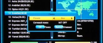
Setting up TV channels on MTS TV can be done automatically or, if desired, the subscriber can do it manually. In the latter case, you will have to enter the frequencies yourself.
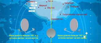
Satellite signal coverage from MTS TV
A brief summary on setting up satellite television from MTS:
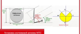
- Fix the antenna included in the kit on the wall of the building so that the heads are located at the required angle to the transponder.
- Place the clamp so that the plate is at an angle of 30° to the horizontal.
- The azimuth of the “antenna” tilt must be set to the vertical by 1°.
- Place the plate at a 137° angle.
- Turn on the TV and check the signal quality.
- If the required quality is not available, you need to rotate the antenna 1 degree and check the signal quality at each step.
- If you received the “TV from MTS” set, then the TV channels should be set up automatically.
- If you need to set up television yourself, use the transponder data suggested above.
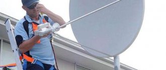
Detailed instructions on how to set up a satellite dish from MTS.
Types of satellite bands
For television, the following satellite bands - C (signals with a frequency of 3.5 - 4.2 GHz) and Ku (signals with a frequency of 10.7 - 12.75 GHz), which are available in all types of devices used.
Ku - range
The Ku-band is divided into 2 sub-bands - lower Lo (less than 11700 MHz) and upper H (more than 11700 MHz). In this mode, several types of converters are used that are suitable only for the Lo subband, only for the H level, for different types of polarization, universal converters - for receiving the Lo and H subbands and both linear polarizations, and other types of converters.
Position 22 kHz - This register for the Ku-band is used to output Lo to the range of universal converters. If frequencies are less than 11700 kHz, then this register is not used, if higher, it is required. When using other types of converters, the 22 kHz position is usually not used.
Local oscillator frequency - When using universal converters, the specified frequency is LQ1 = 9750, for receiving H signal LQ 2 = 10600. Using converters of other types, different local oscillator frequencies can be set, for example, 10000, 10750, etc. This value can be determined visually from the plate on the converter, where it is also called LQ
Transponders for satellite channels for free viewing of satellite TV in 2021
There are satellite TV channels that you can watch for free, and there are channels that are locked with a static BISS key. Channels in BISS encryption can be freely opened using the internal receiver emulator. In both cases, you need to have an up-to-date table of frequencies and transponders on hand to set up satellite television.
Below is an up-to-date table of transponders, an encoding option, frequency, and a closed or free transponder is indicated.
List of satellite channels and transponders for 2021 for the Eutelsat 36B, 36.0E satellite:
| Eutelsat 36B, 36.0E | ||||
| Frequency | Speed/SR | Channel name | BISS/ID | Standard |
| 11212H | 14400, 3/5 | 2 TV (Georgia) | — | DVB-S2 |
| 11212H | 14400, 3/5 | 1 TV HD (Georgia)** | — | DVB-S2 |
| 11212H | 14400, 3/5 | Rustavi 2 | — | DVB-S2 |
| 11212H | 14400, 3/5 | Comedy | — | DVB-S2 |
| 11212H | 14400, 3/5 | Marao TV | — | DVB-S2 |
| 11230H | 15000, 3/5 | Palitra News | — | DVB-S2 |
| 11230H | 15000, 3/5 | POS TV | — | DVB-S2 |
| 11230H | 15000, 3/5 | Maestro | — | DVB-S2 |
| 11230H | 15000, 3/5 | Imedi TV HD | — | DVB-S2 |
| 11230H | 15000, 3/5 | GDS TV | — | DVB-S2 |
| 11230H | 15000, 3/5 | Comedy | — | DVB-S2 |
| 11230H | 15000, 3/5 | Rustavi 2 | — | DVB-S2 |
| 11230H | 15000, 3/5 | Marao TV | — | DVB-S2 |
| 11766 L | 30000, 5/6 | Info channel Tricolor HD | — | DVB-S2 |
| 11785 R | 27500, 3/4 | Shop & Show | — | DVB-S2 |
| 11843L | 27500, 3/4 | TV Search Tricolor | — | DVB-S2 |
| 11977 R | 27500, 3/4 | Channel 8 | — | DVB-S2 |
| 11977 R | 27500, 3/4 | HSR24 (Home Shopping Russia) | — | DVB-S2 |
| 12174L | 4340, 3/4 | TNV Tatarstan | — | — |
| 12226L | 27500, 3/4 | Tricolor info channel | — | — |
| 12226L | 27500, 3/4 | Telemaster Tricolor (Mpeg 4) | — | — |
| 12226L | 27500, 3/4 | Promo Tricolor (Mpeg 4) | — | — |
| 12265L | 27500, 3/4 | Shopping Live (Mpeg 4) | — | — |
| 12303 L | 27500, 3/4 | Union | — | DVB-S2 |
Transponders for satellite channels for free viewing on satellites AMOS 4W, ASTRA 4.9E, HOTBIRD 13E for 2021:
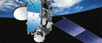
Principle of operation
A satellite transponder is a set of components installed on a satellite, which is designed to automatically receive and transmit a signal at a certain frequency. Resembles a satellite component equipped with antennas.
Any satellite is equipped with a certain number of satellites broadcasting in one frequency spectrum or another.
Due to the introduction of this broadcasting technology, the number of satellite channels on one satellite has increased by an order of magnitude; it is possible to broadcast about a thousand channels from one orbital position.
The principle of operation of a satellite transponder is the following - a satellite TV signal, which is concentrated on the transponder antenna, and due to its dish-shaped shape, is reproduced as if from a mirror to a specific target - the user's receiving dish, which transmits the signal to the receiver, which converts it into one readable by the TV.
The main components of the transponder include:
- antenna for receiving a signal - the main device for receiving a relayed signal;
- power amplifier – amplifies the power of the received signal to a sufficient level;
- duplexer (frequency separation filter) - a device designed to organize duplex radio communications using one common antenna for both receiving and transmitting a signal;
- control processor – selection and change of signal frequency.
Bent Pipe Transponders
This kind of transponder takes over the microwave spectrum signal. It reorganizes the input signal frequency into the RF frequency and then increases it.
Such a device is suitable for relaying both analog and digital signals.
The signal is transmitted from the satellite through several transponders