Is the TV digital?
First, find out whether your TV model supports the DVB-T2 digital broadcast format; this is necessary to receive digital terrestrial broadcasts. At the moment, CETV broadcasts twenty TV channels and three radio stations require an antenna to receive them. This information can be found in the product documents or on the box where the characteristics and capabilities of the product are written. On the website Look at the Russian Federation there is a list of all TVs that support the digital format. You can also find out from the model name by deciphering the product code. Using the Rubin RB-19S5T2C TV as an example, it turns out to have a 19 diagonal, built-in digital tuners T2 and C, as you can see, everything is indicated.
RUBIN TV circuit diagrams
Download RUBIN TV circuit diagrams for free and without registration. Collection of TV circuits:
Rubin 29SCH (VST), Rubin 37FM09T-8 VR.03, ruby 37M04, ruby 37M04-1, ruby 37M05T, ruby 37M06 (T), Rubin 37M06 (T) -2, Rubin 37M07, Rubin 37M09 (T) VR.02 , RUBY 37M09(T) ver.03, RUBY 37M09(T)-1 ver.02, RUBY 37M09(T)-1 ver.03, RUBY 37M09(T)-2 ver.02, RUBY 37M09(T)-2 ver.03, RUBY 37M09(T)-3 ver.02, RUBY 37M09(T)-3 ver.03, RUBY 37M09(T)-4 ver.02, RUBY 37M10(T) ver.02, RUBY 37M10(T )-1 ver.02, RUBY 37M10(T)-2 ver.02, RUBY 37M10(T)-3 ver.02, RUBY 37M10-1, RUBY 37M10-6, RUBY 37M10-7, RUBY 37M10R ver.02, RUBY 37M10R-1 ver.02, RUBY 37M10R-2 ver.02, RUBY 37M10R-3 ver.02, RUBY 37S20 TV COMBO, RUBY 51FM09T-8 ver.03, RUBY 51M04, RUBY 51M04-1, RUBY 51M05T, RUBY 51M06 (T), RUBY 51M07, RUBY 51M09(T) ver.02, RUBY 51M09(T) ver.03, RUBY 51M09(T)-1 ver.02, RUBY 51M09(T)-2 ver.02, RUBY 51M09( T)-2 ver.03, RUBY 51M09(T)-3 ver.02, RUBY 51M09(T)-3 ver.03, RUBY 51M09(T)-4 ver.02, RUBY 51M09(T)-4 ver. 03, RUBY 51M10(T) ver.02, RUBY 51M10(T)-2 ver.02, RUBY 51M10(T)-3 ver.02, RUBY 51M10(T)-4 ver.02, RUBY 51M10R ver.02, RUBY 51M10R-2 ver.02, RUBY 51M10R-3 ver.02, RUBY 51M10R-4 ver.02, RUBY 51TTs-402D,DI, RUBY 54M04, RUBY 55FDS07T(P), RUBY 55FM09T-8 ver.03, RUBY 55FM1 0 , RUBY 55FM10-4, RUBY 55FM10-6, RUBY 55FM10-7, RUBY 55FM10-8, RUBY 55FM10T, RUBY 55FM10T ver.02, RUBY 55FS07T(P), RUBY 55FS10T, RUBY 55FS10T(P) ver. 02, RUBY 55FS10TP , RUBY 55FS10TP ver.02, RUBY 55FS10TR, RUBY 55FS10T,, RUBY 55M04, RUBY 55M05T, RUBY 55M06(T), RUBY 55M07, RUBY 55M09(T) ver.02, RUBY 55M09(T) ver.0 3, RUBY 55M09( T)-1 ver.02, RUBY 55M09(T)-1 ver.03, RUBY 55M09(T)-2 ver.02, RUBY 55M09(T)-2 ver.03, RUBY 55M09(T)-3 ver. 02, RUBY 55M09(T)-3 ver.03, RUBY 55M09(T)-4 ver.02, RUBY 55M09(T)-4 ver.03, RUBY 55M10(T) ver.02, RUBY 55M10(T)- 1 ver.02, RUBY 55M10(T)-2 ver.02, RUBY 55M10(T)-3 ver.02, RUBY 55M10R ver.02, RUBY 55M10R-1 ver.02, RUBY 55M10R-2 ver.02, RUBY 55M10R-3 ver.02, RUBY 55M10R-4 ver.02, RUBY 55S05T, RUBY 55S10T-1, RUBY 55S10T-1 ver.02, RUBY 55SM10-4, RUBY 55SM10-6, RUBY 55SM10-7, RUBY 55M1 0, RUBY 55M10T, RUBY 63DS07T(P) izm.01, RUBY 63S05T, RUBY 63S06T(P) izm.01, RUBY 63S07T(P) izm.01, RUBY M10(T)-4 ver.02, RUBY 106, RUBY Ts-391D , RUBIN chassis KD-035, RUBIN chassis MSh-S05T.
PDF file format. Archive size – 31.5Mb
Next collection of circuits: VITYAZ TVs
Setting up digital channels
First of all, connect the antenna cable to the TV to supply a TV signal. A UHF antenna is required to receive DTV. This can be either an indoor or outdoor antenna, it all depends on your area and the transmitter power on the TV tower.
It is better to configure the settings in Auto Mode, this way the entire frequency plan will be scanned and all available channels will be found.
Let's move on to the settings.
- First of all, select the signal source by pressing the SOURCE button.
- Select DTV to view digital programs. ATV is analogue TV that does not work in most populated areas.
- The next step is to press the Menu button.
- Use the left or right buttons to find the Channel section.
- Next you need to select the broadcasting country Russia, you can also select Germany or Finland.
- The mode should be Broadcast for terrestrial TV and Cable for Cable TV.
- Select the desired mode and click on Auto search.
- Next, select DTV and ATV, you can select one item or both.
- Click start search and wait for the scan to finish.
- To set up cable, you must also select the Setup Type Full.
- We all start scanning and wait for the process to complete.
After the channel search has been successfully completed, you can use the Program Editor option to sort or delete unnecessary channels.
Ruby TV malfunction
Seal
TV Rubin 51M10(T)
Rubin TV malfunctions
Ruby 51M06. Memory cells changed spontaneously
. Replace 24LC16V.
Ruby 55M06. The power supply does not start
. Sometimes it can start up and work for a short time. Replacing TDA16846 and electrolytes did nothing. A detailed check revealed that R807 instead of 1MΩ is 820KΩ, R819 instead of 3.3 KΩ is 1.4 KΩ, R820 instead of 2.7 KΩ is 1.2 KΩ.
RUBY 51M10-2. Doesn't come out of standby mode
. Having plowed through the power supply and found nothing, try unsoldering the small thyristor and turning on the TV for five seconds. Then solder the thyristor again and turn on the TV. Everything should work. There were two devices, both have been working for more than six months. At first I didn’t understand what was happening. Maybe the firmware has gone wrong, and after removing the thyristor, the power supply to the control increased slightly and the processor registered the memory? Or, when the thyristor was desoldered, it was restored. I can’t say for sure, but it’s a fact. You only need to do this if you have really checked all the parts of the power supply.
RUBIN M07. No CP start
. Loss of capacity C700 (1.0×50V)
RUBIN 55M10. After working for 1-2 hours, the picture moves to the right by 5 centimeters
. I installed a radiator on the transformer core, the problem disappeared.
RUBIN 55M06. The TV was repaired after a thunderstorm. The power supply has failed
(TDA16846, BUZ90, CNY17-2, TL431, C547). After replacing all this, the power supply does not start. The reason turned out to be a small leak of the VD808 diode (1N4148), which was discovered after a repeated, most thorough check of all elements.
RUBIN 51M06. The power supply does not start
. At the output of the power supply U=0. There are trigger pulses on the field gate that follow after 2 seconds. At 14k TDA16846 (Vss) a series of pulses appear. Replace TDA16846.
RUBIN 51M04. The malfunction looks like a lack of horizontal scanning
, Is there sound. When you turn SCREEN to the maximum, a narrow horizontal strip 20-25 cm long appears on the screen. D802 7809 turned out to be faulty. After replacing it, everything worked as it should.
RUBIN 37M10. After switching to operating mode, after 2-3 seconds it switches off to standby mode. I set up as a tester to monitor the power filter capacitor of video amplifiers. The process of transition from duty room to worker is clearly visible. The power increases to 115 V, but there is no increase to 180 V due to the operation of horizontal scanning. A single-chip TV based on TDA93*** traced the circuit of horizontal pulses to the base of the output transistor BU508DF. Everything is okay. On the BU508DF collector the pulse swing is only a few volts. The transistor rings absolutely like a whole. After replacing it, the TV started working.
RUBIN 51M10T-2. No power supply starts
. After replacing D802 TDA16846, VT802 BC558B, D801 CNY17-2, the power supply started up. Then the TV turns on, but after 2 seconds. After switching on, it goes into standby mode after another 2 seconds. turns on again, etc. It turned out that the transistor for the VT405 BC547B indication was leaking.
RUBIN 51M06. Power supply for TDA16846. The power supply does not start
. At the output, the voltage is 0. Moreover, there are trigger pulses at the field gate; the power supply does not go into either operating or standby mode, the voltage builds up. — The power supply starts up, produces 120 V, then the power drops and begins to swing. — After a successful launch, it may work normally for some time, and then turn off and the same picture repeats. Defective capacitor C816 - 6800 pF, connected to 4 k. TDA16846. Check by replacement. Notes on the operation of the power supply. R807 - 1M 2%, R820 - 2K7 2%, R819 - 3K3, changes were made at the factory to the circuit 470K, 1K2, 1K5, respectively (see the Rubin 55M10-1 circuit). I don’t recommend changing them to circuit ones
Rubin 55M10. The voltage from the power supply is too high.
(150V instead of 115) The value of resistor R844 has changed (should be 130 kOhm).
RUBIN 55M10
.
When you turn on the TV, a volume control scale with a maximum value appears on the screen
, confusing the commands from the buttons. Transistor VT405 (BC547) is broken; the transistor controls the TV on indicator.
RUBIN 55FM10-8.
The TV is not working, the field effect transistor VT801 SPP04N60S5 is short-circuited on all terminals, there is a break in R805 at 4.7 ohm 5 watts and fuse FU802 at 1A and be sure to check in the secondary circuit at 115 V. diode VD817. After replacing all the parts, instead of SPP04N60S5 - 6N60, VD817-KD226, the TV started working.
RUBIN 55M10-2
.
It buzzes
like a siren when turned on. Replacing the photodetector, adding power.
Rubin 5107
.
Alternating vertical stripes
look like blinds from the film 17 Moments, which prevent you from watching dark pictures. The collective mind has won! The power supply capacitor in the color correction unit has dried out (there is only one there).
RUBIN 37MO10-2
Spontaneous switching of received programs. Discarding the memory, remote control, and keyboard did not help. Replacement of TDA9381PS/N2/1I1156 processor.
MV 0751, aka RUBIN 55M06
. Proc. SAA5531PS/M5, Video processor TDA8842. Doesn't turn on. When turned on from red, the LED lights up green for 2-3 seconds and then starts flashing red. That is, the lowercase starts and the TV goes into protection. In the personnel R608 and D600 burned out. And also, if you find a burned-out 2A mains fuse in these models, and all the parts are B.P. intact, feel free to change the posistor! (a lot of defective ones)
RUBIN 37M10.
The power supply +115V is increased, up to +145V, the power supply is collected on TDA16846, we change the D801 CNY-17-2 (optocoupler), I installed TL111 instead of CNY-17-2, everything worked fine.
RUBIN 51M06
.
Channel settings are lost
. After replacing the firmware with a working one, everything was restored.
RUBY M04.
weak sound
. The decoupling capacitor (of the ULF preamplifier inside the TDA8362) pin 51 has dried out. 10/16V circuit resistance for the variable component has increased, and accordingly the amplifier gain has greatly decreased.
Rubin MV0763
.
Doesn't turn on, LED lights up
. Power supply based on TDA16846, CNY17-2. On duty it gives Ustr=12v, and d.b. about 30c. After switching on, Ustr reaches 60V and that’s it. M/cx and optocoupler are ok. Replace VT805. This model often has a defect - there is no OSD frame synchronization after about 15 minutes. work. In parallel with the frame coil, you need to hang R = 220-330 ohm 1/2w. It seems that as the OS warms up, it changes its parameters.
RUBIN 55M06.
Doesn't turn on.
The indicator lights up . On lowercase in any mode 115v. Does not respond to the remote control and panel buttons. The power supply of the processor is +1.6 V instead of +3 V, it turned out that there is a short circuit in the photodetector. Exchange for import.
RUBIN 51M06
.
The channel setup goes away after 10-15 minutes
. At the moment of leaving, the image is displayed for 2 seconds. blushes. If you manually adjust the channel without turning off, the image appears in red, but in PAL everything is OK. Change quartz 4.43 and VT 402
RUBIN 51M04-3
. After turning on, after a short time it begins to turn off and turn on on its own. As the power supply warms up, the voltage increases from 115 to 150 volts. The reason is a leak in C808 (0.1 µF), which turns into a breakdown when warmed up. There is 1 pin of the power supply chip (voltage regulation).
RUBY 51M10.
Noise, no picture
. The tuner is OK. Change the memory chip on the programmer. Service mode: press the network button and press zero on the remote control.
Ruby 55M10-2.
The standby LED is blinking
, the power supply is restarting. When the power supply is loaded with a 25W light bulb, the power supply enters standby mode, but all output voltages are reduced. The TPI turned out to be faulty, the winding had a 13 Volt short circuit. TPI is simply rewound using acetone and hands.
RUBIN MV-0755.
Processor SAA5531PS/M4.
The sound disappears periodically (MUTE
). The image becomes low-contrast, and at times small horizontal black stripes appear along the entire length of the screen. The culprit turned out to be R113 150th due to an intermittent break.
RUBIN MV 0763
.
Processor SAA5531. There is sound, but no picture
, on video amplifiers 160V, R709, D707 charred. After replacement they heat up again. The C714 turned out to be faulty.
RUBIN MV 0755
.
The OSD graphics are flashing
, the screen is narrowed by frame, a menu pops up spontaneously, sometimes with hieroglyphs. When replacing the processor, L401 was discovered along the way; it was intermittently broken. After replacing the processor in the memory chip, many parameters were reset or corrupted, incl. and geometry. Reflash the memory chip on the programmer.
Ruby 51M04.
Received for repairs after a thunderstorm. The central processor and video processor have failed. After the replacement, everything worked, but when searching for programs in automatic mode, the programs are not remembered. Transistor VT104 (BC548) turned out to be leaking.
RUBY 55S06TP.
According to the owner, at first the color image disappeared intermittently, then the image disappeared, but the sound remained. Over time, the image stopped appearing. When the PIP card was pulled out, an image with poor color rendition appeared. One of the diodes VD505 is faulty, VD504 are installed on the PIP board.
RUBIN 55M06T
.
When turned on, the screen is bright white with LOX
. On the kinescope board, R215 47 ohms burned out in the video amplifier power circuit. Replace TDA6107Q.
RUBIN 51M10-2
. When leaving standby mode, a high appears for a couple of seconds, then goes back to standby mode and everything starts again. The check revealed the absence of personnel pulses, all voltages from the power supply and power supply are normal. Memory, processor, personnel - OK! The reason is a break in L102 along the 8v circuit on the 39th leg of the TDA9381.
RUBIN 51M09
. The TV does not turn on, the standby LED does not light up, the power supply is in working condition. With the thyristor removed, the TV turns on, a raster appears, but does not respond to either the remote control or the buttons. Replacing the processor did not bring any results. The 4 MHz quartz has failed.
Rubin 51M10-3
.
The vertical and horizontal size has changed
. The line voltage is too high (+150V). The value of the resistor going from +115 volts to the optocoupler circuit has changed. Was 130k, became 200k.
Rubin 55M10
.
The power supply produces too much voltage
. The R844 130 kOhm resistor in the secondary circuit was broken.
RUBIN 37M06-2.
It turns on, but there are no graphics, no programs received
, as if the firmware had crashed. Don’t rush to change or reflash the memory, it’s all about the low power supply +3.3V of the ROM, when measured it turned out to be +2.5V, this turned out to be enough for the memory to stop working. The +3.3V voltage stabilizer, assembled on BC547V VT806 according to the circuit, and the VD826 diode according to the circuit have failed; it is better to install a more powerful transistor.
Rubin 55M07
. Power supply based on TDA16846. Malfunction: when turned on, the power supply starts and turns off every 1-2 seconds. At the same time, the LED on the front panel blinks. If you close the K-E VT805, then the TV works. Check VT802, VT803, VD810, VD811, VD812, VD815 and their wiring (I had a broken R826 - 47k)
Rubin 51M04-1
. The voltage from the power supply is too high. C807 faulty (1.0 µF)
Rubin 55M10-2
.
When you turn on the operating mode, the horizontal scan does not start,
after a few seconds the TV goes into standby mode, while the horizontal scan does not even try to start. As a result of the search, it turned out that the TDA9381PS/N2/1I0836 processor is blocked on the bus indicated in the diagram as BeamCut, that is, there is about 80 volts on the grounding of the kinescope and on point 8 of the TDKS (PET22-23) when turned on in operating mode. I unsoldered R704 - the lower case started. Conclusion: leak in TDKS, replace.
RUBIN 55M010.
The horizontal size is greatly increased
and is not adjustable from the service. +V = 160V. The reason is a break in R842 (130 kOhm).
RUBIN 55M10-2.
The picture and
the received signal are not visible. Very dark outlines, although the sound and graphics are normal. Brightness and contrast are not adjustable. When you sharply adjust the accelerator, the image appears for a split second and again darkens almost to blackness. After lengthy diagnostics, it turned out that capacitor C715 failed according to the circuit, rated at 47nf, along the OTL circuit, and went into an open circuit
RUBIN 10T-2.
If the TV is faulty, TDA9351PS\N2\1I0855 is replaced with TDA9381PS\N2\1I1156.
RUBIN 55M06.
The power supply “beeps”
, constantly tries to start, the LED on the front panel blinks in time with the startup. The voltage of 115 volts rises to 70 volts at startup. The malfunction is caused by C818 47.0x25 in the power supply. As a result of this malfunction, the firmware in the 24C08 memory chip may fail. Carefully inspect: TPI T81, horizontal scan transformer T702, horizontal power transistor VT701 for the formation of ring cracks in the soldering of these elements.
Ruby 51M10.
There is no horizontal scan start.
I increased the resistance of R138 from 2.4k to 10k, it is in the voltage divider and connected from the 33rd leg of the TDA9381 to the +8V bus.
RUBIN 55M06
. The TV does not turn on from standby mode; when turned on, the DR indication LED lights up from red to green for 1-2 seconds (the horizontal scan starts briefly, at this moment all supply voltages are normal, including the output IC KR), then flashes red. D600 TDA8356 is faulty.
RUBIN 55M10-1
.
There is no sound on HF
, but from the AV input the sound is normal. Replacement of VT101 BC547C, although when tested it rings normally.
RUBIN-55M06.
It breaks through the TDKS
(PET22-23) onto the ferrite from the area where the high-voltage wire exits. TDKS can be replaced with 154-177V (TV GOLDSTAR), be sure to control the amount of heat. In this case, it was necessary to add another 2nf*1600v to the original capacity of 6.8nf*1600v in the collector of the line transistor.
RUBY 55M0T9T.
PAL disappears
, when the STV2249C cools, PAL appears. Replacing the STV2249C did not solve the problem. After replacing the C130 (18p) with 68 (p), PAL appeared, the TV is working.
Rubin 55M10T-2
. It goes into “cold” mode about the tenth time, or even longer. Then it turns on and if you turn it off and on again, it works fine. The VT700 KT972A turned out to be faulty, although according to the diagram it should be BSR52.
Rubin 55M10T-2
. Malfunction: does not exit the standby mode and emits a weak “tick-tick-tick” with a frequency of half a second. The C822 100μFH35V in the primary power supply unit turned out to be faulty.
RUBIN 55M07-1
.
The power transistor in the power supply is broken
. I replaced it and the TDA16846 chip, I turned it on, it didn’t work. There is a break in R806 1mOhm, start circuit. I also replaced the C819 22nF leakage of about 150 kOhm.
RUBIN 55M07-1
. There is only noise on the screen, no sound, graphics are normal. On the 2nd leg of the tuner (AGC) U=0V. Reason: R146 10k open from +5V to AGC.
Rubin 63S05T
.
Does not turn on from standby mode
(protection is triggered). VD706 (BY228) and Q701 (BU2508A) are faulty.
Rubin 37M06-2.
Problem:
the remote control only works up to a meter
. We replaced the remote control, to no avail. The problem turned out to be a dirty light guide in front of the photodetector.
Rubin 51M04
. Fault: no OSD graphics; When switching channels, the raster disappears for 5-10 seconds, LOH is at the top of the raster. The reason turned out to be the m/s frame scan of the TDA3653C.
Rubin 55M09T
.
After 3-4 hours of operation, the TV spontaneously turns off
into standby mode. The reason turned out to be in the power supply in the VD807 diode (1N4148), in which the reverse current increased when warmed up.
RUBIN 51M04-1.
Increased voltage from the power supply
- faulty C807 (1.0 µF)
RUBIN 55FM09T
. The TV takes a long time to turn on. The voltage from the power supply is too high. (Instead of 115 - 130V) The optocoupler CNY17-2 is faulty.
RUBIN 37M09T-2
.
The buttons on the
TV panel do not switch channels. In “MENU” mode, the buttons work. The problem is a faulty m/s PROM. When I try to reflash it on the programmer, recording does not happen. Replaced it with a new one.
RUBIN 51M10-2
.
Switches off to standby mode after 3-5 seconds
. Launching through the service (menu+0) gives a raster with reverse motion. Replace VT-102. (does not call tester)
RUBIN 55M06.
After connecting to the network, the TV tries to turn on (the red LED on the front panel glows dimly) and after 2-3 seconds. goes into standby mode, the red LED lights up. At the moment of switching on, the horizontal scan voltage increases, instead of 115V - 160V, jumps from 145 to 180. In standby mode, voltage stabilization is normal. The resistors in the stabilization circuits correspond to their nominal values. The culprit in the increase in voltage was the capacitor C836 470.0x16V (capacitance loss up to 22mk) on the 13V supply; the voltage for the stabilization circuit dropped because of it through the VD825 diode. Next is the replacement of the personnel m/s, after appropriate checking of voltages and signals.
Ruby 51M10(T).
A smooth increase in the sound level to the nominal value
occurred 2-3 minutes after the TV exited from standby mode to operating mode. The ULF chip (TDA7056B) turned out to be serviceable. The processor (TDA9381/PS/N2i1...) and memory (24С08) were suspected. Further testing showed a smooth decrease in voltage at pin 20 of the processor (from approximately 5 to 0.25 V). When the minimum value was reached, the sound level reached the nominal level. After reducing the capacitance C111 (between pin 20 of the processor and the common wire) to 0.1 µF (initial value 2.2 µF), the sound level began to reach the nominal level after 7-8 seconds. from the moment it enters operating mode. Due to the fact that the user was satisfied with such work, the processor and memory were not checked.
RUBIN 55FS10TP
.
Poor reception, with snow and distortion. The 38 MHz filter is faulty. Replacement with K2955M.
RUBIN-55M10
.
There is an image, a hoarse sound, an enlarged raster
. Reduced +V to 100V. Leakage of diode VD825(1N4148) in circuit TL431.
RUBY 37MO4-1. Problem: the picture is dominated by green color. Check for open circuit R205, R207 (100k).
Ruby 37/51/55M10
.
Chassis M10. The TV turns on
, the LED on the front panel lights up brightly, there is no screen or sound, and whistling sounds are heard from the power supply. When measuring the voltage at the output of the power supply, it is too high: instead of 115 volts we have 190. It is visually clear that the resistor R834, the transistor VT806, and the capacitor C841 1000.0 × 35 have burned out. The 3.3 volt CPU power supply has a short circuit. All these troubles occurred due to a break in the D801 CNY17-2 optocoupler. The designer of the circuit did not bother to properly protect the heart of the TV, the central processor, with power supply. As a result, we have the following: when the optocoupler fails, the voltage on the VT806 collector increases by more than 35 volts. The transistor breaks through and instead of 3.3 volts, more than 10 volts can be supplied to the processor. It immediately fails.
Rubin 51M10-2
. No sound. Break R117 (22k).
RUBIN 55 FM10 T.
The TV does not turn on, the indicator does not light up
. According to the owner, after a thunderstorm. There is no voltage at the output of the power supply. Faulty: D802 (TDA16846), D801 (CNY17-2) and VS802 (MCR22-8). After the replacement, the TV turned on in standby mode (the indicator lights up red), but when switched to operating mode, the indicator lights up green for seconds, a high-pitched crackle is heard and goes back into standby mode. The transistor VT805 (BC547) is faulty; base-emitter breakdown. After the replacement the TV worked fine.
RUBIN 37M09T-2
. In standby mode, all voltages are normal, i.e. they are 30% of normal, but when you try to turn it on in operating mode, the voltages rise to the operating level for a split second and then immediately drop to zero, which again leads to standby mode. During diagnostics, no overloads were detected. As a result, it turned out that the resistor R823 130 kOhm, increased the value to 250 kOhm, naturally was replaced with a more powerful resistor to avoid repetitions, this is not the first time this has happened with this chassis.
RUBIN 55M06
.
After 20-25 min.
The TV turns off and the power indicator starts blinking red. The TV may turn on immediately or after a few minutes. Then back to the cycle of TV behavior. Remedy: Replace C816 47.0x25V, C825 10.0x50V, C827 100.0x35V, C701 100.0x35V. Soldering all visible microcracks in the board. R801 was burnt - replaced.
Rubin 55M10T-2
.
After a thunderstorm, the power supply did not work
due to TDA16846 and CNY17-2. After installing these parts, the TV started up, but the channels began to switch spontaneously due to D101 type TDA9381 PS/N2/1I1156. After replacing the D101, channels switched normally, but the volume quickly decreased to zero. When increasing the volume with the remote control, it decreased again to a minimum. If you press the volume + on the TV, you switch channels. There was a VT405 type BC548B in the breakdown, it is in the circuit 7 legs TDA9381.
RUBIN 55M06T
. Does not turn on from standby mode, the LED lights up red. Capacity loss by capacitor C818 is 47.0x25V.
RUBIN 55M09-1
.
It does not turn on from standby mode
, the LED turned green and immediately changed color to red and blinked periodically. When checked, the food turned out to be overpriced. Reason: increased its rating R823: 130 kOhm (was 180 kOhm). After the repair, the high power supply was missing. The STV2249C video processor turned out to be faulty.
RUBY 55FS07T
.
Does not turn on from standby mode
. The reason lay in the breakdown of the TDA8351 frame scanning chip.
RUBIN 51M04
.
No sound
. The TDA7056B IC is faulty.
RUBIN 51M04
.
The sound wheezes
. The 6.5 MHz audio filter in the radio channel is faulty.
RUBIN 37M04.
Doesn't respond to commands from the remote control
. The photodetector has power, but there are no pulses at its output. Replaced. I would like to note from this malfunction with photodetectors (this, by the way, also applies to video recorders) that they are not always at hand of the right brand and the right size. So, we install any suitable size, sometimes it is necessary to resolder the power supply and output due to their mismatch, and everything will work. Verified.
RUBY 63S05T
chassis MSh-S05T.
The screen does not light up
. Is there sound. A burnt resistor in the OS circuit R717 15K 1Wt was visually detected. The width of the IOH is twice the norm. The reason is a broken correction capacitor C714 0m33 in the same circuit. It was he who brought the SR out of resonance. After replacing the TV worked fine.
Ruby 63S05T.
The screen does not light up, the accelerating voltage is about 230 V, at the cathodes it is about 150 V) according to the control points everything is normal, with the exception of the reverse pulse (the duration is increased to almost 20 µs). The malfunction is a break in capacitor C708 in the circuit of the primary winding of the liner.
Setting up an old Rubin TV
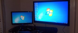
To watch digital channels on an old TV, you need a DVB-T2 digital set-top box; its cost is now around one thousand rubles, so there is no problem purchasing it. The television cable will need to be connected to the antenna input on the set-top box itself, because now it will act as a tuner, and the TV will be a monitor. Therefore, you will have to use two remote controls. You will use the remote control for the set-top box to set up channels and subsequently switch programs, while the remote control for the TV is only needed to turn it on and off.
How to connect.
There are several ways to connect a tuner to a TV receiver, but you should always consider what connectors are on the TV. After all, those cords that will be in the purchased set-top box, namely tulips, will not be enough for connection. Since many Rubies are equipped only with a Scart input, and consoles may not have it. Then you need an RCA-Scart adapter. It is not expensive and can be purchased at an electrical goods store.
After connecting, you need to configure the digital set-top box itself, and select the reception source on the TV. To do this, take the remote control from the set-top box and enter the Channel Settings item to start Automatic Search. You can also use Manual Search to enter the multiplex frequency. As a result, your Rubin TV will start showing high-definition digital TV channels without any image and sound interference. Read more about connection here .