Hi all! I recently purchased a high-quality audio system for my TV, and the question immediately arose - how to properly connect an optical cable to the TV. Firstly, fiber optic cable has a number of advantages over copper wires. Because of this, the data transfer speed is higher, and therefore the quality will be better. Secondly, optical fiber is almost completely protected from electromagnetic and radio influences. Therefore, there will be no interference or unnecessary sounds during transmission.
Therefore, if you love good and high-quality sound, then “optics” is just for you. Of course, connecting it won’t be difficult, but here’s how to lay it out correctly, and how to choose the right one - that’s what I’ll talk about today in the article, so I advise you to read it from beginning to the very end.
We also have a general article about fiber optics from Blonde.
History of the system
Until recently, fiber optic cable was not perceived as a tool for high-quality sound transmission. It is known that fast data transmission is possible only with light. Optical technology was first used in the photophone developed by Alexander Bell.
Optical telephone communication proved the possibility of transmitting a signal through the air, but the inventor’s idea itself did not take root. The physicist's achievements began to be used for communication between ships, but nothing more.
The widespread use of fiber optic technologies began only in the mid-20th century, and a major breakthrough that brought digital audio out to the masses occurred in 1980 with the invention of fiberglass wire, which was capable of transmitting a light signal.
Despite the fact that the optical input celebrated its 40th anniversary, it is still considered the best in terms of analog sound transmission quality, which cannot be matched by the “tulip” HDMI cable, which appeared much later.
Switches
If splitters divide the input signal simultaneously into several outputs, then switches allow you to send a signal from the input to the selected output, or vice versa - from the selected input to send the signal to the output. They are used to switch the audio signal path, when, for example, it is necessary to route sound to one or another effects processor.
The simplest switch is the so-called AB Box. It allows you to direct a signal from the input to one of two outputs, or connect one of two signal sources to one receiver. For example, AB Box DOD 270 is capable of sending a signal from one of two sources to one output or sending an input signal to one of two receivers. All three connectors (A, B, Com) for connecting sources and receivers are jacks. Switching is done by pressing the pedal button.
Basic operating principle
An optical cable connected to digital audio out consists of a shell and a core.
Accepted standards for TV input, the same for Samsung, LG, and other manufacturers, consist of several stages of information transportation:
- generation of a light signal from an electrical one;
- its retransmission from output to input without loss of power or distortion;
- reception of a signal by an incoming device;
- reverse transformation of the signal into an electrical one.
An optical cable connected to digital audio out consists of a sheath and a core. During production, attention is paid to the complexity of connecting connectors, with which you can connect two devices to each other.
Violation of technology significantly spoils the quality of transmitted sound, making the use of optical connections useless. That is why music lovers purchase industrial-cut cables of a certain length.
Adapters
After cables and connectors, adapters are the most common switching devices. As you add equipment, you may find that you need a cable with an unusual set of connectors. This is where adapters come to the rescue.
These devices are designed to connect devices with different types of input and output connectors. Adapters have a small, often cylindrical body, at the ends of which there are connectors of various types. The most common are adapters from XLR to three-pin quarter-inch jack and from RCA to two-pin quarter-inch jack. Often found (mainly for use with headphones) are adapters from a three-pin minijack to a three-pin quarter-inch jack. There are adapters with other combinations of connectors.
The use of such adapters is possible only if the input and output parameters of the devices match, that is, the inputs and outputs must have the same nominal signal level (for example, linear), transmit the signal in the same way (symmetrical or asymmetrical) and match each other in input and output impedances ( impedances). If these conditions are not met, signal transmission may be of poor quality. Thus, if the nominal levels of the input and output signals do not match, sound distortion or an increase in noise level may occur, and if the input and output impedances do not match, signal loss may occur. A classic example of improper use of adapters is connecting an electric guitar with passive pickups with a relatively high output impedance (5-25 kOhm) to the line input of a device with an XLR input connector and a relatively low input impedance of 10 kOhm, using an XLR-jack adapter. There are several errors in this connection, the main one of which is the discrepancy between the input impedance of the device and the output impedance of the guitar (the input impedance in this case should be much greater than the output impedance, at least ten times). Other special devices are responsible for this, with the help of which similar connections can be made. These are matching devices.
Advantages of optical output
The main advantage of fiber optic audio transmission lines is the almost complete absence of sound distortion from electromagnetic fields, which are abundantly present in the human environment. Here, cables with metal conductors can noticeably lose to fiber optic systems in high-quality audio signal transmission. As a result, the speaker system will produce distorted sound.
In addition, when using an optical transmission channel, complete galvanic isolation between the transmitting and receiving devices is achieved. This also has a positive effect on the quality of audio signal transmission. Parasitic interference from bad ground buses is the scourge of audio equipment. The optical systems themselves do not create electromagnetic interference.
results
The following models were identified as test winners: Chord USB SilverPlus, Furutech GT2 USB, XLO UP4U USB, Nordost Blue Heaven USB. The criteria for choosing these particular cables are the most stable and smooth behavior in various conditions and a clearly good effect on the sound in terms of such parameters as detail, dynamics, smooth processing of the frequency range and the correct construction of the scene in all its nuances. Although it would probably be more correct to assume that this is not so much a positive effect on the sound as the absence of a negative influence. The models awarded with the sympathy prize - Qed Performance Graphite USB, Wireworld Ultraviolet USB, Atlas Element USB, showed either similar results in most respects, or have some interesting character features, which can also be usefully applied in practice
and of course, in the case of all cables, it was simply impossible not to pay attention to the price. When a cable costing, for example, 2,600 rubles during the test at all stages turns out to be better than a cable costing tens of thousands of rubles, this is both unexpected and definitely deserves attention
The test results as a whole came as a surprise to me. I have never made such large and detailed comparisons of USB cables before; in my system, playback from a computer plays a secondary role, and this is the only case when I did not select a cable, but immediately installed a decent, in my opinion, option, simply on the principle of “so that was". However, it turned out that the effect on sound in this case is very clear. Of course, in any case, it is much less significant than the influence of speaker and interconnect cables, but there is certainly an influence. How can this be explained? There are many options - most likely due to the interactions between the signal and supply lines due to the design, as well as the effects of interaction between the power supply of the transport and the DAC. and maybe something else. I think that not all developers of the tested cables have a complete understanding of the processes taking place. We also need to touch on the topic of running-in, “warming up”. Of course, some processes are taking place, but I was unable to clearly formalize them by ear and hear such pronounced differences as with analog connectors and even networkers.
But when reading this test, it is worth remembering that with regard to file playback, factors such as the quality of rips, the format being played, the software used and its settings, the implementation of file transport, are in total much more important and significant than the cable connecting the transport and the DAC.
Types of fiber optic cable
To send an audio signal over an optical channel, the sound is first converted into digital form, then, using an LED or solid-state laser, it is sent via an optical audio cable to the signal recipient - a photodetector.
Fiber optic conductors are divided into two main types:
- Monomode;
- Multimode.
In multimode light fluxes may have a spread in wavelengths and trajectories, which can lead to signal distortion over long conductor lengths. The light emitters in such sound transmission channels are LEDs, inexpensive and durable semiconductor devices. The length of the connectors does not exceed 5 meters. The diameter of the central light-conducting fiber is 62.5 microns. The outer shell of the light guide has a size of 125 microns.
For your information. The main advantage of multimode cable is its relative low cost, which is why it is widely used.
In a monomode conductor, light rays move rectilinearly, signal attenuation and distortion are minimal. The diameter of the light fiber is 1.3 microns, the signal wavelength is also 1.3 microns. Such a connector can be longer than a multimode connector. The light source in this case is a semiconductor laser, emitting signals with a strictly regulated wavelength. However, a laser is a more expensive and less durable device than an LED. As a result, the system becomes more expensive than a multimode system, although it has better parameters, in particular, the length of the conductor can be tens of meters.
Wireworld Ultraviolet USB 3.0 m (*favourite)
Design
Flat in shape, moderately hard, springy cable. It’s not rigid in principle, but rather due to its flat shape. The shape is due to the fact that the signal and supply lines in the cable are spaced apart and separately shielded. The conductor material is silver-plated oxygen-free copper, the dielectric material is unknown. The connectors are gold-plated, pressed into hard plastic housings. The cable is made in China. Available lengths are 0.5, 1, 2, 3, 5 and 7 m.
Sound
Neat and at the same time multifaceted, multi-colored sound with extended aftertones. The bass is deep and precise, the mids are open and transparent. The upper frequencies are iridescent and detailed, but without harshness. In general, the sound is fast, light and detailed, but without coldness or lightness. Musicality, integrity and unity are clearly present. Despite all the emotionality, there is no excessive brightness, and the sound does not tire after prolonged listening. The stage is a little wider and deeper than the average, but it cannot be considered too wide or deep. Everything is proportionally correct, precise and neat, the plans are readable, and the images are three-dimensional and textured. In general, a very good result, except that on rare recordings excessive brightness appears from somewhere, and the neutrality of the presentation disappears a little.
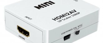
Comparison with HDMI
Modern manufacturers provide a wide choice when connecting audio devices through a home theater. As a result, you can get amazing results. The most popular method at the moment is connecting via an HDMI cable. This way you can transmit not only audio, but also the video signal is transmitted in high resolution.
When equipment with such an interface appeared on the market, optical fiber and its audio output faded into the background, since the wire can only transmit an audio signal, and separate switching is required for video.
But, despite the fact that the connection standard has been in use for 30 years, it is still relevant today. Optical wire is still used to switch up to 7.1 channels of high-resolution audio.
The wire is used due to the use of conventional receivers that have high quality and an optical input on the port. If a person loves good sound on his TV, it makes no sense for him to replace these devices with new ones. It is worth noting that most players or HDTVs and game consoles still use an optical port.
When you turn on radio equipment or a TV, interference may occur due to poor or no grounding. In such situations, a hum begins in the speaker system.
It is necessary to isolate the equipment using an optical wire. HDMI, which is familiar to many, cannot cope with this task. Speakers with an optical input are more reliable. Previously, this method was used to connect equipment to a music center via an optical cable.
Thanks to its unique parameters, the sound quality between the optical cable and HDMI is very good.
Therefore, the old TV cable has not lost its significance in modern days. You can easily connect your home theater to your 2021 TV. The picture and sound quality will be very high.
Expert opinion
Selecting speakers for your TV and how to connect them is enough once. Most likely, the user's preferences will not change and the selected method will be sufficient to meet the minimum needs.
A different situation arises if the user has advanced requirements from acoustics (for example, the habit of watching movies with high sound quality or listening to music in the best possible way). In this case, connection methods can be combined if the necessary equipment is available.
So, what type of connection should you choose?
The answer depends on the system you have. If you need to make a choice strictly between coaxial and optical connections, choose the first option. In our experience, a coaxial connection usually provides higher sound quality than an optical connection due to greater detail and increased dynamics.
However, we live in an era focused on maximum convenience. HDMI has become the standard for all audio and video devices today, and it seems reasonable to use it as long as all components in the system have it.
HDMI's functionality, upgradeability, and simultaneous audio and video capabilities make it easy to avoid cluttering cables around your devices. And most importantly, you don’t have to sacrifice quality.
Video setup
Before you start adjusting the image, turn off the default automatic settings - manual optimization will allow you to achieve the optimal image. The picture for testing can be uploaded to a flash drive, and it must be connected to the TV via a USB connector. To set up your video yourself, you only need to adjust 5 basic parameters:
- boundaries;
- brightness;
- contrast;
- color correction;
- definition.
By adjusting these settings, you can watch TV through your home theater with an ideal picture.
Borders
In the right and left corners of the image there are arrows that should touch the edge of the display, but with only sharp ends. If the size is chosen incorrectly, the clarity will noticeably decrease, as a result of which the picture will be cropped. To change the boundaries, go to the menu. You are interested in the following sections: Overscan, PtP, Full Pixel, Original.
If you set the scaling incorrectly, the image clarity will noticeably drop. An illustrative example:
Brightness
By correctly adjusting this parameter, all shades with clear contours will be visible in the lower part of the image, for a total of 32 of them. Low brightness is a catalyst for increasing the gray color, due to which the picture merges in dark areas.
Excessively increased brightness will cause gradations to merge in the light areas of the picture.
Contrast
Setting this parameter follows the same principle as optimizing grayscale. Correct adjustment requires visibility of all elements of the scale. If the setting is incorrect, some areas of the skin will change to negative.
After completing the settings, go back and look at the brightness indicators - it is possible that they will change. Then check the contrast further. Example of low contrast:
Optical digital connection
In an optical digital connection, data is transmitted through a fiber optic cable (the fibers of which can be made of plastic, glass or quartz) using light. In this case, noise from the source is not transferred to the DAC circuit, as can happen with a coaxial one, so it is reasonable to use it when connecting the device directly to the DAC of a soundbar or AV receiver.
Traditionally, in DC systems, optical cables are used to transmit compressed multi-channel audio in Dolby Digital and DTS formats. Those with a Toslink connector (Toshiba Link) connect to the corresponding ports of the source and AV receiver. A good starting option is the QED Performance Graphite Optical cable.
Many manufacturers have moved to HDMI as the primary connector type, but optical outputs are still regularly found on devices such as game consoles, Blu-ray players, set-top boxes and televisions. The corresponding inputs can be found on the amplifier or DAC side - for example, in sound bars or AV receivers.
As with coaxial connections, one of the problems with optical connections is the lack of bandwidth to transmit lossless audio formats, such as Dolby TrueHD or DTS-HD Master Audio, which contain most soundtracks on Blu-ray discs. In addition, the optical connection is not capable of transmitting more than two uncompressed channels to the PCM. Finally, the optical cable can be damaged if it is bent too much.
What and how is transmitted via S/PDIF?
To guarantee the correct transmission of stereo sound from a CD, it was enough to provide a speed of 150 KB/s, but the developers played it safe and included a reserve for bandwidth. S/PDIF can carry not only the uncompressed stereo signal from a CD, but also multi-channel audio in 5.1 or 7.1 using compression. As well as a certain amount of additional service information, such as the track number, a flag about the permissibility of copying, the presence of compression, and the number of channels. The total information flow can theoretically reach 1.536 Mbit/s. Just one and a half megabits per second - by modern standards this is a ridiculous figure.
It's even more fun to study the protocol from the inside: stereo audio transmission was implemented using PCM pulse code modulation. Data was transmitted in packets of 32 bits each, of which 24 transmitted data, and 8 transmitted service information. If there was less data (some compacts were written in 16 bits), then the rest of the packet was filled with zeros. Not very rational, but effective - the broadcast signal was clocked through service bits, so it could have a very different sampling rate. And although the protocol hardware only supported the transmission of a PCM stereo stream with specific sampling frequencies (32, 44.1 or 48 kHz), they managed to squeeze multi-channel into it.
DVD audio and video media use multi-channel audio in 5.1 or 7.1 format, which is quite successfully compressed according to the Dolby and DTS standard, and transmitted through initially stereo S/PDIF. Yes, it compresses so well that the bit content is even lower than 16 bits. The missing bits are again filled with zeros.
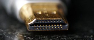
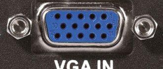
What does the optical output look like on a TV?
The TV has a large number of connectors. One of them is for optical signal transmission. This port is easy to recognize thanks to the trapezoidal plug, which is labeled Optical Audio, Digital Audio Out , or Toslink .
When the device is turned on, a red light will appear around the port to let users know how to connect the device. Therefore, connecting an optical cable to a TV is a simple matter.
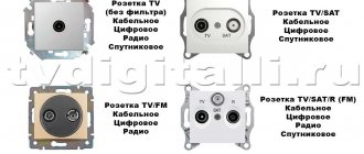
Types of inputs and connectors
First you need to determine what ports the TV is equipped with; based on this, the optimal method for connecting the speakers will be selected. Modern TV models are equipped with universal interfaces that allow you to connect different types of speakers:
- digital interface HDMI ARC (Audio Return Channel);
- special purpose connectors - Scart, RCA;
- standard jack for connecting headphones and headsets;
- line input.
The connectors connecting the tulips allow you to connect speakers that are not equipped with an amplifier. The main thing is that the user chooses the right acoustics; its power should not exceed the established range. If the TV has an output for tulips, but the acoustic device does not, use an adapter.
The last two methods are relevant when the device is not equipped with other connectors. Quite often, old equipment with a built-in amplifier is connected this way.
Using the HDMI ARC interface, you can connect a modern system to the plasma, in particular home theater speakers that can broadcast truly high-quality sound. Not all TV device models are equipped with this connector. A regular HDMI input will not work for this.
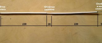
Optical cable parameters for a high-quality connection
To connect an optical cable to the device while maintaining high sound performance, you need to follow the following rules:
- The length of the wire should not exceed 10 meters. The best option is 5 meters. In this case, the quality of signal transmission will remain unchanged. Also, some manufacturers produce thirty-meter cables that transmit the signal without interruption. But the quality will depend on the receiving device.
- The thicker the cable, the longer it will last.
- The highest quality options are additionally equipped with a shell made of nylon fabric.
- It is important to pay attention to the type of core. Suitable options are silica or glass. They significantly exceed plastic ones in quality.
- Bandwidth must be high. A good cable has between 9 and 11 MHz. This indicator should be chosen if a multi-channel sound system with a significant sampling frequency is installed at home.
Compression varieties
Relatively expensive products due to their complex design. But the characteristics of such outputs compensate for any expenses at the initial stage of acquisition.
They have the following advantages:
- Anti-corrosion coating.
- Operation up to 3 GHz.
- Additional protection against moisture.
- Shielding is better compared to conventional cables.
- The temperature range is pleasingly wide, from -40 to +70.
- The breaking voltage is higher when compared with cables.
Analog connectors
At each end of a balanced analog cable you will find 1 of 3 connectors
- XLR “male”
- connects to
equipment inputs - XLR “female”
- connects to microphones and
equipment outputs - TRS
- connects to both
inputs
and
outputs
.
Each of these connectors has 3 contact points
, transmitting signals from the positive, negative and ground wires that I talked about earlier.
- XLR male has 3 pins
- The XLR “mother” has 3 sockets
- TRS has 3 surfaces known as tip, ring and sleeve
Unbalanced cables typically use a single connector, such as a TS connector
, commonly found on instrument/guitar cables.
Further…
Qed Performance Graphite USB 1.0 m (*favourite)
Design
Thin, flexible, slightly springy cable. Externally neat, but made to be completely invisible. The conductors are made of 5N oxygen-free copper. The design uses triple shielding. And the word Graphite is clearly present in the name for a reason - apparently, the inside of the cable is damped with small graphite granules. The presence of damping fill can be heard if the cable is shaken vigorously. The connectors are gold-plated, pressed into plastic cases. The cable is manufactured in China. Available lengths are 1, 1.5, 2, 3 and 5 m.
Sound
The sound with this cable is deep and transparent, airy. Good detail and dynamics are immediately noticeable. The bass is very good - neat, structured and fast. The mids and highs are smooth and open, without being tight or harsh. In general, no coloration or distortions in the tonal balance are felt. The sound is comfortable and not tiring. The stage is wide, deep, with precisely defined images and well-separated, regular shots. There is also unity, in the sense that the sound is not disassembled into parts and detail, but without harshness. Different genres are reproduced equally smoothly without any audible preferences. With the emotional presentation, everything is also in perfect order; what the musical work suggests is what is felt.
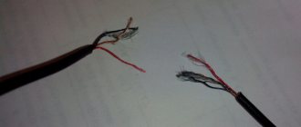
Causes of failure
Users may experience that after connecting the S PDIF connector, the sound may be lost. Possible reasons:
- incorrect connection of speakers or TV;
- foreign object inside the connector;
- old firmware;
- disabling the main device from Windows or in the BIOS;
- failures in the audio processing service in the OS;
- old or crooked sound card drivers.
To determine the cause of the failure, you need to carry out diagnostics using the program's diagnostic utility or special equipment.