What is a satellite converter and what is it used for?
The satellite converter provides signal reception, which is reflected from the surface of the antenna and is transmitted in amplified form to the satellite television tuner. This is a complex mechanism that involves the basic laws of physics. You can buy such a converter at an affordable price.
The main characteristic of the converter is additional noise, measured in decibels. When there is little noise, the image on the TV is slightly distorted.
In science, a converter is defined as a receiver that processes a satellite signal. There are actually two devices in a single monolithic unit.
The first device amplifies the signal received from the satellite. Here the level of additional noise plays the main role. At lower values, there will be much less interference, - 0.3 - 0.5 dB.
The satellite converter is also referred to as LNB or low noise unit.
The second device converts wave frequencies. With their help, the signal is transmitted to the receiver or TV via remote access. An offset satellite dish is optimal for signal transmission. Here's a basic explanation of how it all works:
The converter makes the received signal stronger. This helps compensate for losses in the cable that connects the antenna to the receiver.
The receiver introduces its own noise into the signal. They have constant power. The satellite signal from the antenna alone is not strong, so it becomes weaker inside the cable, hence it needs to be amplified.
However, the device introduces its own noise into the signal, so it is important that it is small. The converter can be purchased from different brands.
Operating principle of an antenna converter with two outputs
The device also converts frequency. This is a very important function. From the usual ranges the signal goes into the L range.
This is a rather complex device that consists of several parts. Its design includes an irradiator, a waveguide and the converter board itself.
Converter chip
The feed is a kind of secondary antenna that catches signals sent from the main one.
The converter amplifies and converts a high-frequency signal into a lower-frequency signal, for example, a 12000 MHz signal is converted to a frequency of 1250 MHz. It serves the purpose of preventing the signal from being completely attenuated in the cable. Ideally, the TV receives high-quality, high-definition signals.
The converter also switches polarization. The channels not only have different frequencies, but also different polarizations. Some are polarized vertically, others horizontally.
It is important how the converter is rotated. The directions differ in different places on the earth's surface.
To begin with, we will select this converter for the signal that comes from the selected satellite. Or rather, from its selected transponders.
For clarity, let’s take another look at the table of transponders for the Express AM 22 53.0°E satellite and select the converter necessary to receive the signal.
To determine the type of converter, we need two parameters from this table. This is the frequency and the type of polarization. I have marked the required columns in green.
As can be seen from our table, the transponder frequency is in the range of 10974 ... 11481 MHz (megahertz). We look at the table below of the “C and Ku” ranges and determine which of these ranges the frequency of the selected channels belongs to.
The selected frequency spectrum 10974 ... 11481 MHz belongs to the Ku band standard, from this we determine that the converter we choose must support exactly this frequency range.
Quite often, at least at the time of writing this topic (since in the C band the signal comes mainly from old satellites, and it is used less and less), both of these frequency ranges may be present in the transponder tables of one satellite. That is, both the range is C and the range is Ku.
In this case, you will have to choose which transponders suit you best. This means that the converter will be either “Ku” range, or “C”. If you want to receive a signal from all transponders, then in this case you need to purchase a two-band converter. And that means a satellite dish
should have a diameter of 1.5... meters (since, for the C-band, an antenna of a larger diameter is needed). As a rule, dual-band satellite converters are much more expensive.
Now, regarding polarization. According to the table, we see that on the Express AM 22 53.0°E satellite there are two types of polarization. These are linear vertical (V - Vertical), and linear horizontal (H - Horisontal).
Both of these polarizations are combined in one type of converter - a universal linear converter. With it, we will be able to receive a signal from almost all transponders from this table.
If you come across transponders with circular polarization, then you need to use a circular converter. Or another way to call it a circular universal converter (since it also uses two types of polarization), which supports circular right (R - Right) and circular left (L - Leftl) polarization.
In the case when you want to receive a signal with both linear and circular polarization, you will also need a converter that supports both of these polarizations. As a rule, such a converter has two pairs of independent outputs, from which signals received in linear and circular polarizations are taken separately. To connect such a converter, with two outputs, to one input of a satellite receiver, you will need to use a special DiSEqC switch, which will connect your receiver to one output of the converter, then to another (more details...).
DiSEqC switch - Serves for remote switching between different receiving devices. For example, between two, three... (etc.) satellite antennas, converters, as well as a converter with two or more outputs.
At first, when I still had little experience, I purchased a converter not with linear polarization, but with circular polarization, that is, a circular universal converter (Circular Single LNB). With such a converter, there could be no question of receiving a signal with linear polarization. At the time I was installing the satellite dish
, there were almost no such transponders (meaning open Russian-language ones, with circular polarization), well, perhaps “NTV+”, but now, at the moment (i.e. at the time of writing this page), it was already working with all its might quite popular, the Russian project “Tricolor TV”, broadcasting several program packages from one transponder (one free, and paid START and NIGHT), in this case this converter, Ku band, with circular polarization, would be suitable. In any case, at that time, I needed a universal linear player. On top of that, my receiver did not support the encodings in which channels with circular polarization were transmitted.
Subsequently, I had to buy a universal converter, with linear polarization, capable of receiving the transponders I needed at that time.
As I already mentioned, installing a satellite dish
, I not only wanted to watch the satellite TV channels themselves through the receiver, but also, by installing a DVB card in my computer, have access to the satellite Internet, thereby making the most of the opportunities that now presented themselves.
Therefore, when using a satellite dish
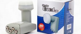
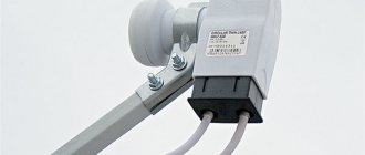
, I needed to output from the converter, not one signal, but two. To do this, I had to purchase a special converter with two independent outputs, designed to receive signals with linear (V,H) polarization. It consists of two identical converters, in one housing, with one irradiator (Photo 7).
Photo 7 Satellite converter with two independent outputs.
In principle, it was possible to go another simpler way, leaving on the antenna
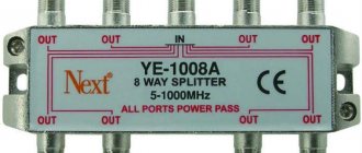
converter with one output. For such cases, there is a special splitter, the so-called Splitter (Photo 8). But this method has its pros and cons. And here's what.
Photo 8 Splitter - signal splitter.
The advantage of such a splitter would be: firstly, the relatively low price of such an upgrade (at the time of writing this page), about 80 - 150 rubles, secondly, there is no need to change the converter, risking the tuning of the satellite dish
, and thirdly, simple manipulations during installation.
Now, as for the shortcomings. To figure this out, you need to know a little about the operating principle of the converter itself, or rather, the circuit diagram of its power supply directly in this case.
Converter power supply
Next, let's look at the example of linear (V,H) polarization in the power supply circuit of a satellite converter. In principle, it's not that difficult.
Imagine some kind of electronic device, for example, a pocket receiver. Without what will it not work, even if the entire electronic circuit is working? The answer here suggests itself. Of course, if we don't put batteries in it. That is, we will not provide it with normal power supply. The converter is also no exception, like any electronic device, it also needs power. Now imagine that in the receiver, you want to switch from one radio station to another, what will you do in this case... of course, we’ll turn the tuning knob or use the toggle switch to switch to another range. What about the converter? After all, you can’t climb onto a satellite dish to twist or switch anything.
So the developers came up with the idea of controlling the converter remotely, using the same cable through which the satellite signal travels. So, in order to control the switching of the type of polarization, the converter is supplied with power of different voltages, as if in the example of a pocket receiver (imagine if it has neither a tuning knob nor a range switch), when switching from one radio station to another we will change the number of batteries in the power compartment. Let's say one radio station will be broadcast if the receiver has four batteries, and another if there are six.
In a converter with linear polarization, if vertical (V) polarization is used, then it is supplied with power equal to 13...14 volts, and if horizontal (H) polarization is used, then 18...19 volts. Here I think the principle is clear to you.
Now, about the main disadvantage of using one converter for two receiving devices through a splitter, so to speak, what is its essence.
The point here is that the satellite converter can only be powered by one voltage at a time. That is, either 14 volts or 18 volts. This means that the polarization can only be either vertical (V) or horizontal (H). And this is what we get. If on a satellite receiver you will watch a TV channel broadcast in vertical polarization, then on a computer with a DVB card (or on a second receiver), you can simultaneously use vertical polarization, although the TV channel may be different.
This disadvantage becomes very significant if one satellite dish
, with a converter (which has one output), through a splitter, used for two apartments. One neighbor wants to watch football, another wants to watch some movie, but the polarizations of these channels are different (it’s not far from a quarrel).
The advantage of a converter with two independent outputs is that it does not matter which output has which polarization (in this case, linear “V” and “H” are meant). The disadvantages include the rather greater weight than a converter with one output, and of course the higher price. At that time, it cost me 980 rubles (whereas for a converter with one output, I then spent 270 rubles).
So, if you have two satellite receivers, then in this case it is better to use just such a dual converter.
…
Well, all that remains is to attach our converter to its holder, and of course to the “L-shaped bracket” itself of the satellite dish
. Below you can see the option I gave for assembling the satellite converter mount by left-clicking on the image (Photo 9).
Photo 9 Converter on a satellite dish
.
Next, we will learn how to understand the specifications of satellite converters...
Parameters of satellite converters
(marking of satellite converters)
Below in the photographs (Photo 1 and Photo 2), two satellite converters are shown, with circular and linear polarization, Ku-band. As you probably noticed, they are no different in appearance, except for the inscriptions on their markings. These converters are designed for installation specifically on an offset satellite dish
.
Due to the fact that offset and direct-focus antennas have a significant difference in the way the converter feeds are mounted, the converters themselves are divided into those used for offset antennas and those used for satellite antennas
.
Converters for installation on an offset satellite dish
Now, let's determine by what criteria the type of satellite converter is determined. “Photo 3” shows the marking location for this model.
Photo 3 Place of marking of the satellite converter (for this model).
For greater clarity, let’s enlarge the image of the converter markings (Photos 4 and 5).
Judging by the logo, the converter was manufactured by a fairly popular satellite equipment manufacturer at the time, Golden Interstar.
Here are four main criteria that I try to pay attention to when choosing a satellite converter:
The first two determine the parameters of the signal that will be received from the selected satellite. The third and fourth determine the quality indicators of the satellite converter.
- Type of polarization - Circular (right and left), and Linear (vertical and horizontal).
- Frequency range - C or Ku.
- Noise figure - the higher this figure, the lower the quality of the received signal.
- Gain - the higher this coefficient, the more the received signal will be amplified (it should be taken into account that both the signal itself and the noise are amplified).
Below in the image of the converter markings (Photo 6 and Photo 7), I have highlighted some values in different colors.
Where:
1. CIRCULAR - circular polarization. UNIVERSAL - linear universal polarization.
2. NF - 0.2 dB - noise figure (measured in decibels). The lower the noise figure, the better the signal will be. There are converters with a high noise figure, for example 0.3 dB (or the completely outdated 0.6 dB), they are usually cheaper, but... I would not skimp on this parameter (tested by practice).
Note: The noise of C-band satellite converters is measured not in decibels, as in Ku-band converters, but in degrees Kelvin (for example, noise figure 10K).
3. 11.7-12.50 GHz - the frequency range to which this satellite converter belongs. In this case there will be a Ku-band.
Note: The manufacturer decided not to indicate such a parameter as “gain” on the converter labeling.
As you can see, not all parameters are indicated on the converter markings on its body. Therefore, when purchasing it, look not only at the tag, but also at the markings indicated on the packaging box (Photos 8 and 9), or on the passport. For more detailed information, using the example of a satellite converter with two independent outputs, left-click on the image.
(marking of satellite converters) 1. Marking of the “Golden Interstar” satellite converter of linear polarization with two outputs.
2. Marking of the “Golden Interstar” satellite converter with circular polarization.
We will need the remaining parameters when setting up the satellite receiver (receiver), where I will continue discussing converters in more detail.
Now, install on the satellite dish
the converter you have chosen, and it’s time to stop at choosing a satellite receiver (receiver), that is, which model you want to use specifically for your requirements.
What types of satellite dish converters are there?
A converter, more precisely called an LNB, is needed in order to convert the wave frequency “Ku” (10...13 GHz) or “C” range (3.5...4.5 GHz) into 0.95...2.5 GHz, which allows the signal to be transmitted with minimal losses along the cable up to receiver.
This makes it possible to use an inexpensive coaxial cable and give it a length of up to 20-30 meters so that the signal is not lost. TO\
All converters vary in noise. Their diversity is also great in another way.
The following converters are available:
- Converter for “C”.
- Converter for “Ku”.
- Universal".
LNB satellite antenna converter C band
It is necessary to determine in which band, “Ku” or “C”, it is used. The big difference between the devices is their operation in different frequency ranges. The frequency converter works in a wide variety of weather conditions.
Single-phase to three-phase voltage converter - Diagram
Single-phase to three-phase voltage converter circuit. (10+)
Single-phase to three-phase voltage converter - Diagram
Contents :: SearchSafety :: Help
This diagram, like any other, may contain errors. If you find them, please write to us. Subscribe to the news to stay informed about corrections and updates to the material.
Attention! Assembly of the device requires skills in the field of power electronics and involves contact with high voltage, which can be life-threatening for both the engineer and the users of the device. Make sure you have the required qualifications.
The circuit is made on the basis of a pulsed power source of sinusoidal voltage. I advise you to familiarize yourself with its diagram.
| We present to your attention a selection of materials: The practice of designing electronic circuits The art of device development. Element base. Typical schemes. Examples of finished devices. Detailed descriptions. Online payment. Opportunity to ask questions to the authors |
This circuit is not a three-phase inverter
, but can be used to develop it. If, instead of a power factor corrector, a 12 or 24 volt to 600 volt converter is installed at the input of the device, which can be obtained on the basis of a resonant inverter by adjusting its output voltage from 310 to 600 volts, then you will have an excellent three-phase inverter.
Schematic diagram of a single-phase to three-phase voltage converter
The converter produces a three-phase voltage of good sinusoidal shape 370 V, 1.5 kW (in total for all three phases). The voltage of 370 V rather than 380 was chosen based on the fact that to obtain 380 V you need to supply the circuit with a constant voltage of 620 V. But power switches and half-bridge drivers at 600 V are much more common. And reducing the supply voltage by 3% does not matter for most devices.
The circuit uses three identical blocks. The elements on these blocks have the same designations on the diagram. The circuit was drawn by altering the circuit of the sinusoidal voltage source. I didn't have the heart to renumber the elements. So some numbers are missing. Forgive me for this.
The principle of operation of the satellite converter
The converter collects the waves, converts them into signals of electrical origin, which transmit the signal to the receiver. The LNB converter is placed at the focal point of the antenna, where the waves are focused. The signal is amplified in the converter and converted to a lower frequency.
To transfer a signal from C or Ki to the L-band, you need a local oscillator that generates a radio signal. The mixer helps to obtain the third signal, which is the difference of the first two. In the end it works out.
In the Ki band, in the opposite way, the local oscillator frequency is calculated from the frequency of the signal received from the satellite. There is another feature there. It is impossible to transfer the entire Ki-band to the L-band.
Either the converter has one local oscillator and does not cover the entire Ki-band, or the satellite signal goes into the L-band only partially, the bottom or top of the range is used.
The second type of converter is universal; it has 2 local oscillators, the second of which covers the upper Ku band. The ranges are switched using an electronic key controlled by a special signal.
Inside the converter there is a metal structure. The filling of the device is hidden in a metal case, where the output for the F-connector is inserted.
The converter may have a different number of outputs. Sometimes the number reaches eight.
Satellite converter for 2 and 8 outputs
It is very convenient for everyday use. Sometimes there may be several tuners that allow you to optimize the signal for several TVs.
Universal satellite converter
Converter parameters for Tricolor TV
In addition to the already indicated noise level, the head for the Tricolor plate is selected according to a number of parameters. Some of them are critical for receiving broadcasts from this particular satellite television provider.
Frequency range
Each converter operates with a specific frequency band. It is better for Tricolor to choose a device that meets the broadcast standard of all Russian satellite television providers - this is the so-called KU range.
Advice! Products with such markings can be offered both by frankly handicraft Chinese manufacturers and by famous brands. Practice shows that malfunctions occur very rarely in models of the mid-price category, so it’s definitely not worth focusing on a high price tag and brand name.
Polarization
Tricolor broadcasts in circular polarization. Converters of another type, linear, are not suitable for receiving broadcasts from this provider. Polarization is indicated directly on the device body. The inscription Circular means circular, and Universal means most often not suitable for Tricolor subscribers.
Number of outputs
As mentioned above, to watch programs on one TV, a converter with a single output is sufficient. If there are two or more TVs in the house, it is recommended to buy a device with the required number of ports. There is no need to skimp on this feature. Splitters - dividers in some cases cannot provide adequate signal quality to the consumer.
Noise level
Today the Tricolor company offers channels in UHD quality for viewing. The requirements for receiving such a signal are very high. If a subscriber plans to subscribe to HD and UHD channels, he will need a low noise LNB (LNA) converter.
Many manufacturers claim a noise level of 0.1-0.2 dB for such a device. However, this is most often a marketing ploy, and in practice the figure ranges from 0.3 to 0.5 dB. It is this range that you should focus on in order to buy a device with the optimal price-performance ratio. A simpler converter is suitable for receiving regular broadcasts. The permissible noise level ranges from 3 to 5 dB. The price of such products is very affordable.
How to check the converter for functionality
It is very easy to check the converter for serviceability. If you have problems with the TV's reception of the signal, you need to see if the problem is really with the converter.
First you need to visually check the cable going from the receiver to the antenna to see if it is broken anywhere. If the cable is intact, you need to check the head of the dish, then the contacts with the wires; there is an easier option, namely, change this head and see if the signal has changed. Then you can understand whether the cause of the problem is in a broken converter or in another unit.
How to choose a satellite head and check the satellite antenna converter for functionality, converters for satellite antennas with two, three and four outputs:
Frequency division of converters
The year 1977 was marked by the meeting of an international conference that adopted rules for systematizing satellite activity. Naturally, the procedure was preceded by numerous studies by the participants. The passage of waves of different lengths into the atmosphere was studied. Just kidding, punch through the air to the soil from space! Geostationary satellites do not hover so low above the Earth. Why do they float? The earth rotates tirelessly, to compensate for the movement, the satellite has to move after the orbit. The speed is enormous, because in 24 hours it must make a full revolution.
The radius of the Earth is approximately 6370 km. The shape of the planet is not round, not even elliptical. Experts say: it looks more like a pear, tapering towards the North Pole; it simply lacks a suitable body of geometry. It is believed that the shape of the earth is the geoid. Now we will give the value of the orbital radius; understand, the counting is carried out from the conditional center of the earth, located at the intersection of the equatorial plane and the axis connecting both geographical poles. The planet's center of mass is located in a different place; geographic poles should not be confused with magnetic poles (indicated by a compass).
In order for the satellite to begin to rotate around the Earth, it is necessary to inform the object of the First Cosmic Velocity. The device must move in orbit, working out the angular velocity of the planet’s rotation. Make one revolution every 24 hours (23 hours 56 minutes). Smart heads have calculated: the orbital radius should be 42,160 km at an altitude above sea level of about 35,790 km. Because the Earth rotates on an axis through the poles, the only orbit possible is geostationary satellites. Located strictly above the equator. To make a satellite in another orbit immobilized relative to the Earth, one will have to constantly make great efforts and spend a host of resources.
This does not mean that spacecraft hanging above the equator at an altitude of 35,790 km are deprived of human attention. Special stations constantly monitor the position and orientation of the satellites, making adjustments to the movement if necessary. The corrections are so small that the fuel is enough for the spacecraft to operate for many years. Now we know why the plates of the Northern Hemisphere look south. Not strictly along the meridian, but in the direction of the equator.
Since the prime meridian passes through the axis of the passage instrument of the Greenwich Observatory, located in Great Britain, Russia lies in the Eastern Hemisphere. The list of satellites broadcasting in this space is given by Wikipedia. Not everyone will be visible from any point on the earth’s surface at the same time; choose your provider carefully. Otherwise, you won't be able to watch TV.
How to choose a LNB, what to look for
Noise figure is the main parameter for choosing a converter. It is important to take into account the frequency range, phase noise, current used, and polarity when choosing. The most important components are noise figure and gain. In a good way, the noise figure should be indicated on the packaging.
Specification
If it is not listed, you should not buy the device. At the same time, a low coefficient does not guarantee that the converter will be of high quality. This parameter is tested only in laboratory conditions.
Therefore, it is better to buy devices only from places that have been tested and have proven themselves well. A universal converter can be bought inexpensively on the Internet and in radio parts stores. This is the best option.
How to choose a satellite converter:
VHF converter circuit
The article describes the simplest VHF converter for receiving radio stations in the “European” range of 88-108 MHz on domestic radios. The design was repeated more than 200 times over several years.
In the converter circuit, the absence of scarce parts, ease of execution, setup without instruments, and stability of the circuit are the main features of the described device. Several years ago, an urgent need arose - to ensure the reception of radio stations in the European part of the VHF range (88-108 MHz). Initially, these stations began to appear in the countries of the former socialist camp, like mushrooms after rain, and then in our country.
At first, a big obstacle to progress was the lack of this range in the Soviet standard, and therefore the lack of mass radio receivers to receive it. A VHF converter came to the rescue. At one time, circuits of varying degrees of complexity were tested - from three transistor to one transistor.
It turned out that in most cases the simplest single transistor option was optimal. It should be noted right away that the diode mixer in most cases was significantly inferior to the transistor frequency converter in terms of frequency transmission (conversion) coefficient and harmonic spectrum.
According to the diagram in Fig. More than two hundred (200!) converters were manufactured on the site. Not a single discrete element of the circuit was selected, and deviations in values reached up to 20%. Transistors were installed without checking the gain.
The frequency converter is made on transistor VT1 type KT315 with any letter index. All circuits are without cores. The input circuit P and the output circuit L4 are wound with wire PEV-1-0.8. The communication windings L2, L5 and heterodyne circuit 13 are wound with PEV-1-0.18 wire.
Number of turns of coils: L1 - 6 turns; L2, L5- 2 vit.; L3 - 3+13 vit.; L4 - 7 vit.
First, on a 04 mm mandrel (a drill shank was used), coil L1 is wound turn to turn. The leads are cleaned of enamel, and the coil is soldered into the board. Then the L2 communication coil is wound. The drill is not removed from the reel yet.
The end of the wire is cleaned of enamel and soldered into a circuit board. The communication winding is wound between the turns of the loop coil. Then the second end of the communication coil is soldered into the board, and the mandrel drill is removed from the coil. The outer turns of the contour coil are slightly moved apart.
Coils L4 and L5 are wound and sealed in the same way.
The local oscillator coil L3 is wound on a plastic rod with a diameter of about 3.5 mm (vinyl rods from snowblower brushes were used). After stripping the insulation of the leads, the coil is soldered into the board. Then the remaining parts are installed. The length of their pins is minimal, so the height of the board is very small.
Specific Models
The satellite dish converter from Tricolor is popular because of its reliability, and you can buy it at an affordable price. It will not cost much, but will provide home owners with a high-quality signal.
Satellite head from Tricolor
ALYNO satellite television has a combined C+Ku converter based on two converters.
It has a dependent output “Ferret direct focus Twin-Twin”, which provides constant signal reception in two ranges at once: C and Ku. Works only in conjunction with the passive multiswitch 4/2. Made for offset antennas. Polyethylene caps.
Converter General Satellite GSLF-51E with waveguide diameter: 40 mm (standard); connector type: 75 F-type is also popular among subscribers.
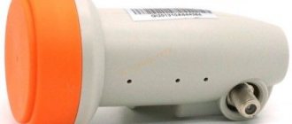
Galaxy Innovations GI-301 converter is a circular polarization converter. It is very convenient to use in everyday life.
DIY VHF converter
A VHF converter assembled with your own hands according to the diagram in Figure 1 allows you to receive radio stations in the range of 65-73 megahertz to a receiver with a range of 88-108 MHz.
Picture 1
The input circuit of the VHF converter is tuned to the center of the 65-73 MHz range. From it, the received signal is sent to a frequency converter made on transistor VT1, Figure 1. The local oscillator of the VHF converter is built on transistor VT2, it generates RF oscillations with a frequency of 30 MHz.
From the output of the local oscillator, the high-frequency signal is supplied to the frequency converter, namely to the source of transistor VT1. As a result of the addition of the input signal and the local oscillator signal at the drain of transistor VT1, signals from VHF radio stations in the 65-73 MHz range appear, transferred to the 88-108 MHz range.
This signal is removed from capacitor C3 and supplied to the antenna input of the receiver with a range of 88-108 MHz.
To wind coils L1 and L2, frames with a diameter of 4 mm and a length of 10 mm are used, equipped with a tuning core made of brass 5 mm long. L1 contains 5 turns of PEV-2 0.4 wire with a tap from the first turn, L2 is wound with the same wire as L1 and contains 10 turns with a tap from the second turn.
After you assemble the VHF converter with your own hands , you need to set it up. To do this, by adjusting the L2C6 circuit, the local oscillator frequency is set in the range of 29-31 MHz. The input circuit L1C1 is adjusted to the middle of the received range.
If you need a VHF converter that allows you to receive signals in the 88-108 MHz range to a receiver with a range of 65-73 MHz, then in the circuit in Figure 1, capacitor C1 must be replaced with a capacitor with a capacity of 15 pF, and when setting up the converter, the input circuit must be adjusted to that part of the range 88-108 MHz in which radio stations are received.
Go to the Radios section
Source: https://radio-ostrovok.jimdo.com/radio receivers/VHF-converter-with-your-hands/
Design and installation on the antenna
Electromagnetic radio waves fall onto a mirror. Since its shape is spherical, the signal falling onto the mirror area is reflected only in a single direction, forming a beam focused at one point.
The necessary device is placed in the “focus” - the satellite converter itself. This beam falls on him. The main elements of the converter are the feed, the waveguide through which the signal travels, and the electronic unit that converts the waves into pulses.
The converter converts frequency, polarization, and provides a high-quality signal. Designed for watching TV in high quality.
Errors during selection and installation, how to avoid them
The quality of the case is often chosen inappropriately.
Workplace - street. During use, the device is affected by temperature changes. Therefore, the device body must be of high quality.
The removable cover from the sun's light must be resistant to radiation. Therefore, you should again choose high-quality material.
Important! Any depressurization of the device will allow atmospheric moisture to enter, which will lead to failure.
The color of the body should not be bright, otherwise it will attract birds that will peck at the bright plastic.
Before setting up, it is important to see how capable the device is of operation.
Important! A working device shows a signal even when the antenna is not tuned to the satellite.